Espeasy: powering ESP32 only on USB
hi , i have ESP32 esp-wroom32 with yellow pins:
https://www.aliexpress.com/item/32845423155.html?spm=a2g0s.9042311.0.0.27424c4dYMzqRH
i upload succesfull the bin file of last release for ESP32
but i find an issue to power up the ESP:
1) if i use the USB cable, it boot up normally, and i have no problem on using it.
2) if i use the 5v and GND pins the ESP continue to reboot and red led continuos blinking.
I guess that there is a problem about Wifi connnection in case i use pins intead of usb port.
If i connect using usb port, then wait around 20seconds, and the connect the 5v and GND pin, and after that disconnect the usb cable, the ESP will not reboot end become stable.
It's a "known issue" ?
it's related in someway to firmware?
thanks
 megamarco833
All 91 comments
How do you power it?
What kind of power supply and cables I mean.
Also is there anything else connected to the ESP32 board?
Especially during WiFi connection the ESP may draw quite a bit of current (short peaks of up-o 500 mA)
If the power supply you're using is not really powerful or the cables used are quite thin, then the voltage to the ESP board may drop.
Such a voltage drop may cause all kind of undefined behavior.
The reason why I mention any other connections is that if there is somehow some indirect connection to other nodes or devices then there may be current flowing through places where you don't want.
Can you show a picture of how it is connected?
Also try to measure the voltage over the pins where you power it. (preferably at the pins on the ESP board)
 TD-er
on 11 Jul 2019
TD-er
on 11 Jul 2019
How do you power it?
What kind of power supply and cables I mean.
Also is there anything else connected to the ESP32 board?
i power it with a power supply 230v-5v stabilized using dupont cables. i'm confident that is not here the problem because i use same stuff to power on esp8266 (nodemcu or wemoss d1 mini) without any problem.
ESP32 has nothing connected
Especially during WiFi connection the ESP may draw quite a bit of current (short peaks of up-o 500 mA)
If the power supply you're using is not really powerful or the cables used are quite thin, then the voltage to the ESP board may drop.
Such a voltage drop may cause all kind of undefined behavior.
ok, but i use the same stuff to power on ESP8266.
ESP8266 is different compared to ESP32 ?
The reason why I mention any other connections is that if there is somehow some indirect connection to other nodes or devices then there may be current flowing through places where you don't want.
Can you show a picture of how it is connected?
Also try to measure the voltage over the pins where you power it. (preferably at the pins on the ESP board)
i measure 5,1V and it can be ajusted from 5,5V to 4.5V, nothing change in this range.
thanks for your support.
p.s. anyway i bet that the problem could be inside the wifi connection, because if i use usb cable to power on ESP32 (5v and gnd disconnected) i wait 15-20seconds (wifi in this time will connect) then connect 5v and GND, and after that wait 5seconds and disconnect usb cable.
in this case the ESP32 still connect with 5v and GND
if i use directly 5v and GND ESP continue to boot in a loop.
megamarco833
on 11 Jul 2019
Just a warning about the power switch you just tested.
It is good to know there seems indeed to be something fishy here (might be the USB to serial does behave badly and does perform a reset), but be aware that supplying external 5V to an USB cable connected to your PC may cause damage to your PC or USB hub if you're using one.
Do you have some USB power bank you can test?
Some of these power banks do also set some defined state on the data pins to allow the device to pull 500 mA or more. Maybe powering it via the USB port but not sending any data can help to test if the USB to serial chip is doing something strange here.
TD-er
on 11 Jul 2019
thanks again for reply, but sorry maybe i explain in not a good way.
if i use only usb, i do not have any issue. all is working and boot correctly.
if i do not use usb, but only 5v pin the esp continue to boot and i never succeed on login to its web page.
the only way to use 5v pin is:
1) connect only usb cable and not 5v pin
2) wait 20-25seconds with only usb cable connected
3) after this 25seconds connect the 5v pin and still mantein connected usb cable
4) wait 5seconds
5) disconnect usb cable and still mantein connected 5v pin
6) now the esp32 will be poweron only by 5v and it still connected without any problem
megamarco833
on 12 Jul 2019
I understand it, but I just want to eliminate the possibility the PC does something to the USB=>serial chip on the ESP.
If you're using an USB power bank (or just about any USB power plug), it will not communicate to the USB=>serial chip, but is does set some resistors to the data lines indicating the USB device can switch to > 100 mA. That's the only communication then. It also does use the USB power lines.
I know these USB=>serial chips can perform a reset on the ESP. You can easily verify that by opening a serial console to the ESP and see it will reboot.
A next test could be to use some "charge only" cable, meaning one that does not allow data communication. But that's something not generally available.
My assumption is that the USB=>serial does perform a reset when it powers on, or maybe even keeps the ESP reset triggered when it is not powered.
I can imagine the USB=>serial chip is not powered when using the 5V lines instead of powering it via the USB port.
TD-er
on 12 Jul 2019
A next test could be to use some "charge only" cable, meaning one that does not allow data communication. But that's something not generally available.
ciao, i did some tests using different power charge and connect them directly to ESP32, with this the ESP is not booting and continue goes to a boot loop
only way to power one is using cable connected to USB computer.
My assumption is that the USB=>serial does perform a reset when it powers on, or maybe even keeps the ESP reset triggered when it is not powered.
I can imagine the USB=>serial chip is not powered when using the 5V lines instead of powering it via the USB port.
do you have an idea how to solve it?
thanks
megamarco833
on 15 Jul 2019
You can try running the basic blink sketch in the Arduino toolkit to make sure it is not an issue with ESPeasy.
But I am afraid it may be a (hardware) design flaw on the board you have.
TD-er
on 15 Jul 2019
You can try running the basic blink sketch in the Arduino toolkit to make sure it is not an issue with ESPeasy.
But I am afraid it may be a (hardware) design flaw on the board you have.
ok thanks, this evening i'll try to make this test.
anyway i ordered a new one ESP32 wroom to test if it's the hardware problem or not :-)
p.s.
i see the latest build on github: Release mega-20190715
there are not inside the bin file compiled?
why?
thanks again
megamarco833
on 15 Jul 2019
About the build issues.
I also noticed there were no binaries inside, so I just fixed the build script.
The update to PlatformIO 4 did move the location where the files are built, so I had to update the build script.
Edit:
If you ordered the same module from the same vendor again, you may still run into the same problems.
I think the design of the module may be flawed here.
TD-er
on 15 Jul 2019
hi, related to module, no, i chanege the vendor.
mine module has also pins that are yellow. the new one should be black.
Related to build issue, can you please substitute the zip file on github, or i'll wait for tomorrow build?
thanks
megamarco833
on 15 Jul 2019
There will be a build tomorrow anyway.
I don't think anything related to your issue has changed in the nightly builds.
If you like, you can test this build I made for testing the build script, but I don't think it will make any difference.
TD-er
on 15 Jul 2019
Hi guys. Sorry disturb both of you.
i also have same problem.
Powered by USB no problem. But using 5V pin has problem which wifi always reset.
i read your discussion above but dont have any solution or suggestion to solve. Hope somebody can help this.
 manmoncang
on 15 Jul 2019
manmoncang
on 15 Jul 2019
I'm running ESPeasy on an ESP32 board with OLED and battery. I have the same problem. Connected to USB the wifi starts fine, connected to a strong power supply I don't get wifi, but the display shows 'ESPeasy'.
 plin2
on 12 Aug 2019
plin2
on 12 Aug 2019
Did anyone try to connect external rs232/ttl converter?
What is printed on the terminal before hang?
Does espeasy react for commands from terminal?
 uzi18
on 12 Aug 2019
uzi18
on 12 Aug 2019
I'm running ESPeasy on an ESP32 board with OLED and battery. I have the same problem. Connected to USB the wifi starts fine, connected to a strong power supply I don't get wifi, but the display shows 'ESPeasy'.
@plin2 This looks like the ESP does boot, but crashes.
Maybe you can start a ping from one node, to see if it actually does get an IP-address?
Via rules you may also try different things like acting on events as system#boot to set a LED.
Maybe we can then see how far it does get into the startup process.
I've re-read this issue again and I think it may be possible to power the unit by powering over 3.3V instead of 5V.
This way the USB controller chip does not get power.
My theory is that the USB controller chip does create some pin state at startup which may trigger the reset-circuit.
Such a circuit is meant to help putting the node into flash mode, but it may now trigger a reset.
TD-er
on 12 Aug 2019
@TD-er it is also possible that usb converter chip mess up something.
uzi18
on 12 Aug 2019
is your converter chip CP2102 or CP2104?
uzi18
on 12 Aug 2019

@TD-er it could be related to auto program feature
uzi18
on 12 Aug 2019
@TD-er: I had a ping running while connecting the ESP32 to the power supply. No response. Just tried it again and it works. I think I had given the device a fixed IP address and changed 'Restart WiFi Lost Conn:' to ON. Just trying to revoke these changes and test again. Can't reproduce the connection probem right now. Will have to try later again.
By the way: I use the micro USB connector and a standard USB cable.
Just lost the connection again. Power off/on and I got a reconnect. Turned 'Restart WiFi Lost Conn:' to ON again. We'll see how thta goes.
plin2
on 12 Aug 2019
@TD-er it could be related to auto program feature
That;s indeed my hypothesis.
The circuit on the lower left of your posted part of the schematic.
TD-er
on 12 Aug 2019
I had my device running in the power supply until now and it still has the wifi connection and DHCP-based IP address.
plin2
on 12 Aug 2019
I had my device running in the power supply until now and it still has the wifi connection and DHCP-based IP address.
what's happen if you remove the power supply 5V and after a while reconnect again the 5V external?
the ESP32 will work again, or become in continius boot loop?
what's the working configuration that are you using now? (eg:'Restart WiFi Lost Conn: is on or off ?; etc....)
megamarco833
on 12 Aug 2019
State
Restart WiFi Lost Conn:
no fixed IP adress
detached device from power, after reattaching it doesn't connect to wifi, 'ESP Easy' on the display is coming/going in an app.r 4.5 secs loop
attaching it via USB
immediate wifi connect
attaching it to power
no wifi connect
setting a fixed IP address
attaching it to power
doesn't connect to wifi, 'ESP Easy' on the display is coming/going in an app.r 4.5 secs loop
after a while 2 pings went through
device doesn't respond to ping again
now the display is permanently showing 'ESP Easy', accordin to my access point the device is connected, pings are not successful
using the on-board power switch off->on
steady display of 'ESP Easy', connection to access point, no ping
plin2
on 12 Aug 2019
How are you "attaching it via USB" ?
Is that on a:
- computer
- USB hub
- "smart" charger
If one of those, can you check on the simplest USB charger you can find with at least 500 mA (preferably more) power
TD-er
on 12 Aug 2019
Connection via USB is to my computer. That way I cann use the serial monitor in Arduion IDE to check the state etc.
Well, since I have as working display: is it possible to show the wifi connections state and IP address on the display?
plin2
on 12 Aug 2019
accidenatially plugged it into the other USB port of my computer => no ping response
effect is reproducable
plin2
on 12 Aug 2019
If you're using the Framed OLED plugin, it does update every second the WiFi connection state via the bar-icon in the upper right corner.
When not connected, nothing is shown, otherwise 5 bars indicating the RSSI.
TD-er
on 12 Aug 2019
That "other port" is that the difference between USB2 and USB3?
TD-er
on 12 Aug 2019
Im using the 'Display - OLED SSD1306' device. I have this board: https://de.aliexpress.com/item/32905558379.html?spm=a2g0s.9042311.0.0.2be14c4dGSWZdq
It only shows 'ESP Easy' in line 1.
On the right USB port the device appears as COM6
well, things keep changing. Attached to the löeft port it's still COM6 and it just got a wifi connection and responds to pings
plin2
on 12 Aug 2019
would that give us some help?
on System#Boot do
Let,1,0 // set user variable to initial state of 0
oled,2,1,'reboot'
EndOn
on Wifi#Disconnected do // if no wifi, wait 3 minutes
if [VAR#1]=0
timerSet,1,180
Let,1,1 // set user variable 1 to 1 to prevent re-set of var1 on each event.
oled,3,1,'disconnected'
oled,4,1,''
endif
endon
on Wifi#Connected do // if wifi returns, cancel reboot
timerSet,1,0 // cancel timer
Let,1,0 // set user variable 1 to 0
oled,3,1,'connected'
oled,4,1,%ip%
endon
On Rules#Timer=1 do // if still no Wifi, reboot
reboot
endon
Attached via USB seems to be working, even through in the left USB port I saw the device going into sevarl reboots until it connected. Right USB port works better. I see 'connected' and the IP address.
connected to power supply I see 'ESP Easy', sometimes 'reboot', then on my first attempt no more 'reboot' but steady 'ESP Easy'
Detached and reattached it again. After 2-3 attempts it connected and shows an ip address.
plin2
on 12 Aug 2019
I'm just seeing some rebooting loops while attaache to the power supply. The cycle still is appr. 4.5 secs.
The loop can start after showing
'ESP Easy'
'ESP Easy' + reboot
'ESP Easy' + reboot + disconnected, '', ''
on the display.
plin2
on 12 Aug 2019
Can you see the reboot reason right after it did successful connect to wifi?
It should be on the sysinfo page.
TD-er
on 12 Aug 2019
I had it attached to power, no connection. Then switched it to USB and without reboot I got a connection:
Reset Reason: | CPU0: Vbat power on reset CPU1: for APP CPU, reseted by PRO CPU
-- | --
plin2
on 12 Aug 2019
OK, that's the expected reset reason.
The reason I somewhat "hoped" for was this one:
case RTCWDT_BROWN_OUT_RESET : return F("Reset when the vdd voltage is not stable");
TD-er
on 12 Aug 2019
well, it's not what it looks like:
ANKER 5 port power supply: problems
USB port of computer: ok
smaller 3 port power supply: ok
small 1 port power supply: ok
plin2
on 12 Aug 2019
OK, so it seems the Anker power supply does some communication with the serial port controller.
That's not really a surprise, since Anker is known for their quality products. So it does make sense they do support something more than just 2 resistors on the data lines of an USB port to signal "you may take 500 mA".
The PC port obviously does also do something, but that's not going to crash the USB->serial controller since it will be some kind of USB init sequence..
Can you see what USB->serial adapter is used (as asked by @uzi18 https://github.com/letscontrolit/ESPEasy/issues/2505#issuecomment-520336827 )
TD-er
on 12 Aug 2019
Can you see what USB->serial adapter is used (as asked by @uzi18 #2505 (comment) )
I don't have any documentation for the board. I took a photo and found a TP5400 chip near to the USB port, other one further away an SS54. Is there any technical way to find out?
plin2
on 12 Aug 2019
You can see in the device manager of Windows what driver is used.
The CH340 is a rectangle shaped SMD chip.
The CP210x ones are smaller and square shaped.
I think it is not the CH340, since that one almost never gives issues with rebooting the node.
The CP210x ones do reboot the device by just opening the serial port or rebooting the computer.
TD-er
on 12 Aug 2019
According to Windows it's a Silicon Labs CP210x USB to UART Bridge
plin2
on 12 Aug 2019
And on the chip itself?
TD-er
on 12 Aug 2019
I didn't find the chip yet. There are two without printing on them
- a little silver one (unknown number of pins)
- a little black square one with 28 pins
Does the CP2104 have 24 pins and the CP2102 28?
plin2
on 12 Aug 2019
Yes, that pin count should be right.
- CP2102-GM* QFN28
- CP2109-A01-GM* QFN28
- CP2104 QFN24
TD-er
on 12 Aug 2019
I was thinking, it would not be the first time those popular chips are cloned.
And given it has no marking on them does suggest these adapter chips may not be the real Silicon Labs ones.
TD-er
on 12 Aug 2019
I enlarged the photo of the board but still can't recognise anything like printing on that 28 pin chip...
plin2
on 12 Aug 2019
sometimes photo with flash do the job
if you have some experience you can try to remove both small transistors
uzi18
on 12 Aug 2019
@uzi18: I did use a flash, photo manipulation (contrast, btightness,...), no luck
plin2
on 12 Aug 2019
if it is clone or even broken chip, thats why no marking, do you have another module to test?
uzi18
on 12 Aug 2019
no, that's the only one
plin2
on 12 Aug 2019
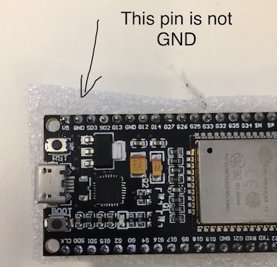
This may be irrelevant, but I encountered the same issue and think my solution may be applicable to others.
The Yellow pinned devkit c sold by aliexpress has incorrect silk screen markings as seen below.
(The pin marked GND is actually CMD).
When connecting GND to a different GND pin, the chip boots as expected.
 yonirom
on 24 Dec 2019
yonirom
on 24 Dec 2019
This may be irrelevant, but I encountered the same issue and think my solution may be applicable to others.
The Yellow pinned devkit c sold by aliexpress has incorrect silk screen markings as seen below.
(The pin marked GND is actually CMD).
When connecting GND to a different GND pin, the chip boots as expected.
Hi, thanks for the info.
But if i do not understand well, if the GND pin close to Vin pin are marked wrong, if i need to power on this esp32 where i connect vin and gnd?
I guess vin (+5v) is correct pin, so i will put here 5v
But for gnd there is only another one pin marked as gnd: close to 3v3, i need to use this one?
Do you know if maybe there is another pin that it is gnd not marked?
Thanks
megamarco833
on 25 Dec 2019
See image below. There are two real ground pins:
(Image borrowed from: https://components101.com/microcontrollers/esp32-devkitc)

yonirom
on 25 Dec 2019
See image below. There are two real ground pins:
(Image borrowed from: https://components101.com/microcontrollers/esp32-devkitc)
Thanks, but mine module seams different...
I bought on aliexpress as esp32 nodemcu
It's like the image fron here
https://circuits4you.com/2018/12/31/esp32-devkit-esp32-wroom-gpio-pinout/
I have two gnd pin, at the bottom, one close to vin and one close to 3v3 like the link that I post above
megamarco833
on 25 Dec 2019
I understand, so these are probably different issues.
The symptoms you described were very similar to what I experienced, so I thought this might help others.
Good luck.
yonirom
on 25 Dec 2019
I think that you are right maybe different module has the same issue : pins are not marked well.
The problem is how i can discover where is the right gnd in my version?
megamarco833
on 25 Dec 2019
hi, i have three different ESP32 bought on aliexpress.
i fash them with espeasy without any problem, but i have a strange behavier when i power on them.
if i use usb cable, no problem at all.
if i use pin Vin and GND with a poer regulator of 5V i can see the web page of espeasy.
for sure is not the power suppy problem, i use this one to power up 6 esp8266, so i can exclude it
i see that if i connect before the usb cable, and after that connect the Vin and GND, the webpage will be visible and ESP32 do not crash.
i would like to use esp32 to connect 8ch relay and 8 switch
i create the task but if i use esp32 powered by USB cable i can sitch on/off the relays, if i use Vin and GND power (plus usb cable, otherwise as i explained usin only pins is not working the ESP32 power up) the relays are working.
these are my device:
https://ibb.co/nb1mH3L
look at the photo you can see same ESP32 wroom32 chip
i have two of those with yellow pin and one with black pins, but the behavier is the same for all my three ESP32
has someone this problem?
can someone suggest me on aliexpress a link where i can buy an ESP32 that can be programmed with espeasy that can use pins as power-up and can use relays+switch ?
thanks
megamarco833
on 22 Feb 2020
Hi, I may confirm issue. When powering Esp32 devboard (board look like upper board of previous comment) with USB port it starts fine and works as expected. USB port may be powered from PC, Phone charger or powerbank - it works always. When powering with 5V through VIN and GND it fails connecting to WiFi network due it do not find it or because authentication error. Scanning for networks returns from zero to two results when powered from VIN. When powered from USB it returns always 4-5 networks. I live in semi-urban area.
I added capacitors to power lines etc, and do not imagine how I could improve startup of device without attaching USB cable.
Updated: I have made sketch, which scans for networks, then tries to connect to my home AP. Problem is seen best with poor AP signal. Testing with external (+5V)power to VIN. If signal is strong connections is made within 1-2s. Is signal is average (-71dbi) connection takes 4s. If signal is poor -78 or -80dbi you cannot connect using external power. If I use USB powering it connects in such weak signal anyway. Problem may be is USB powering and External powering differences, and I think external powering PIN is limiting power to Wifi module used for connection. I would like to hack somehow to solve it, but I have only one board now and dont want to fry it :(
 aliusc
on 1 May 2020
aliusc
on 1 May 2020
I have two different devkit1 boards. I can't recall from whom I bought them, but the one on the left, with the white letters on the black background worked on USB only. The one on the right with (small) black letters ESP32S on a white background works on USB and battery connected to VIN. The battery voltage at VIN was measured at 4.8V
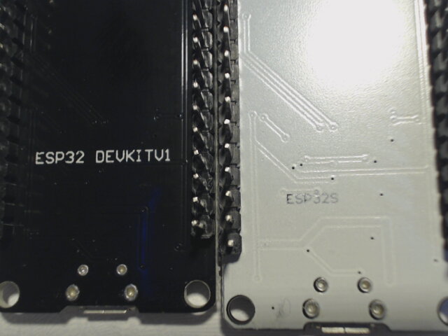
The second image is of the same boards in the same position. The front looks identical.
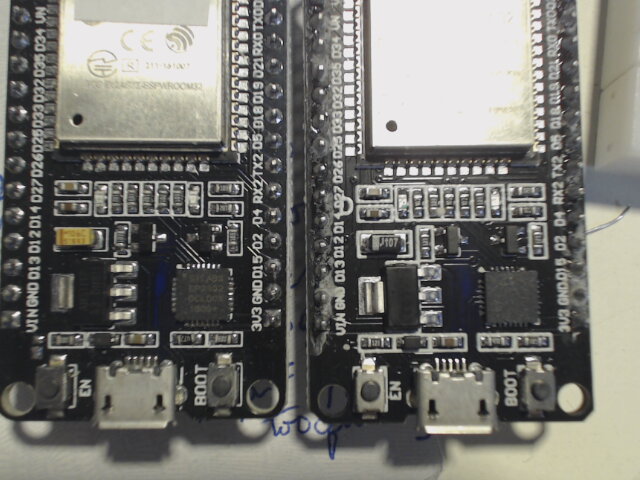
The power regulator (you can't see it in the above images, but with a magnifying glass, they both use AMS1117 3.3v chips) are identical.
I hope this saves everyone a lot of trouble avoiding the same problem that has been bugging a lot of us.
 larryn46
on 4 May 2020
larryn46
on 4 May 2020
Do you try to power on the black one using vin pin with 5.6 volt? Mine work in that condition...
megamarco833
on 4 May 2020
I made a mistake in the above comment. The voltage supplied to both boards was 3.8v, not 4.8v.
larryn46
on 4 May 2020
To megamarco833, I have a power supply that has a voltage of 5.03 volts when nothing is attached. The voltage drops to 4.6 volts when connected to the devkit1 board that is black on the back with white letters. It boots without any problems when the power is supplied to the VIN pin using the GND next to the 3V3 pin. Did you see the above comment that the so-called GND pin next to the VIN pin is really CMD, not VIN? On my board, the two GND pins are electrically connected, so I don't think it matters.
larryn46
on 4 May 2020
Hi, i have three eap32 boards.
One with black pins that look exactly the same of yours on left.
The other two are with yellow pins.
The nodemcu black like your esp32 on right it's the only one that works good with vin and gnd pin.
I use the gnd pin close to vin and i supply with power supply that can be regulated.
If i power with a bit more than 5v it boot using vin and gnd.
My power supply is regulated to 5.4v but sometimes it disconnected after some hours,but the boot is always successful.
So i asked if yoi can power on using a bit more than 5v. Maybe 5.5 or 5.6 can be the best.
megamarco833
on 4 May 2020
So i asked if yoi can power on using a bit more than 5v. Maybe 5.5 or 5.6 can be the best.
Please be aware this will also supply a higher voltage to some sensors than may be connected to the 5V line.
For example SenseAir CO2 sensors may be damaged when supplying such voltages.
So make sure not to have anything else connected to this "5.5V" line.
TD-er
on 5 May 2020
ESP32 with black back boots OK with 5.4 volts on VIN pin
larryn46
on 5 May 2020
So like mine..
It seams that esp32 is requiring a little more than 5v to boot fron vin and gnd
megamarco833
on 5 May 2020
So like mine..
It seams that esp32 is requiring a little more than 5v to boot fron vin and gnd
Are you sure the voltage doesn't drop at the ESP side of the power cable?
You could also test with 5V and some capacitor of 220 - 330uF at the 5V close to the ESP board.
If that does work, then your voltage drops at boot (probably during start of WiFi).
Another option can be to place a small capacitor (1 ... 10 uF) over the EN pin of the ESP32.
This does delay the boot a little so the rest of the board has some time to get a stable power at power-on.
TD-er
on 5 May 2020
I´ve found a solution to the (my) problem.
In my case, ESP32 only boot if you are connected to the USB and with a terminal open. If you just connect a USB power supply, no matter the strong, none of my ESP32s boot at power up but they boot (and run OK) if you then press the "enable" button.
Checking the schematic, you can see that the handshaking, when the terminal is open, makes that cp2102 handshaking (DTR/CTS) generate a low pulse to the enable pin when you open the terminal.
When you boot using only a power supply, ESP32 boots so fast that there are transient errors that make it crash and it is neccessary to delay the boot, generating a long low pulse in the enable pin.
The solution aplied is to solder a capacitor of 470 microF between enable pin and ground (positive terminal in enable pin) so this will keep the enable signal low during enaugh time to stabilize the power up.
I´ve tested with 1 microf, then 2, and finally I just pick an available 470 micros and all is OK, no matter the power supply I use.
 plop510
on 28 Oct 2020
plop510
on 28 Oct 2020
Thanks for feedback... Do you have a photo to see how a where you welded in your hardware? Thanks a lot
megamarco833
on 28 Oct 2020
The back of the main board is really crowded and is difficult to access and get a picture.
For me It´s easier to draw what a did.
I represent the front side but is placed in the back side. I had to choose that ground pin despite of not being the nearest because I didn´t have space to weld.
Regards.

plop510
on 28 Oct 2020
I´ve found a problem with the capacitor value: too big. The value solves the issue with powering from a USB charger (no PC) but avoids Arduino IDE to upload the software on ESP32.
The capacitor value generate a delay of several seconds and is good for normal restart but breaks Arduino bootloader protocol when you need to upload the code. To not enter into many details, that delay makes Arduino IDE not detect the board and it´s impossible to upload any thing.
As I don´t know the vaue of pull-up resistor inside ESP32 Enable signal, I can´t calculate the tau time constant (R*C) to figure out a proper delay, then I´ve decided to divide the Capacitor value 50 times and I placed a 10 microfarad instead of 470 micros. The result is good for both problems:
- Boots from any standalone power suply
- It´s possible to upload code from Arduino IDE.
I´ve been testing thoroughly both cases without any failiure.
Regards, Pepe.
plop510
on 5 Nov 2020


plop510
on 5 Nov 2020
The previous pictures show the Capacitor placement in the system. BTW is a Telescope control system controlled through MQTT.
plop510
on 5 Nov 2020
hi, thanks for your post, but my issue is on using ESP32 without USB cable and using 5v on pins: Vin and GND, so without USB
in this case what value of capacitor i have to connect between EN and GND?
i try now with a electrolitic capactitor of 100v 4.7uF
megamarco833
on 7 Nov 2020
Just try starting with 10uF but reduce the capacitor´s voltage range from 100v to 16v: is enough, cheaper and much smaller.
As a first try, to verify that the problem is in the power up transient, power up the board and, as nothing will start, then press EN and:
- Case 1- ESP32 then starts up correctly: the problem will be solved with the capacitor. It means that EN signal need to be kept down for a while till everithing gets stable. Start connecting a 10uF 16v or bigger (remember that I started with 470uF ...).
- Case 2- the system hungs: maybe the problem comes from the power supply for possible causes:
- low current supported or
- thin/long cables from supply to ESP or
- noisy power supply. In the two last cases, putting a big capacitor between ESP 5v IN and GND will help. Big means 470 uF or more and very very near of ESP pins. Also good sections cables from power supply and ESP will help.
Please, tell me your findings and good luck.
Pepe.
plop510
on 8 Nov 2020
hi, my power supply is this one:
https://it.aliexpress.com/item/33037781855.html?spm=a2g0s.9042311.0.0.27424c4dzGof2O
i think that 5v 10A are more than enough....or i'm wrong?
cables that i'm using are doupont connectors.
right now i'm on a "develop system" where i have:
1 power supply
1 breadbord 5cm X 8cm where i have power supply IN and GND
6 esp8266 (nodemcu)
1 lcd display lcd 2004
5 pcf8574 (connected to ESP)
1 esp32
4 arduino relay 8ch (32relay in total) connected to esp8266
2 arduino relay 2ch (4 relay in total) connected to esp8266
relays are connected using JD-VCC => vcc (relay)->5v (esp, same of power supply) JD (relay) -> 5V power supply GND(relay)->GND power supply.
I used this type of connection to use optoisolator
https://1.bp.blogspot.com/-K1NqhKO3jFs/XPP5vt-Mr1I/AAAAAAAEZ1A/H2JJSVDq9EcDJr5oCupFlS5EL1f62nL7gCLcBGAs/s640/Connections.png
is it all correct?
could be that cables are too much long?
is the power supply good enough?
or should i use two poer supply? 1 for powering ESP and another one to power arduino relays?
megamarco833
on 8 Nov 2020
Hi Marco,
Step by step: As I told before, try first to verify that the problem is in the power up transient. Just power up the board and, after several seconds, press EN and see what happens:
- 1: If system starts working OK, it means that power up process transient is affecting a fast boot on ESP => just put a capacitor mentioned between EN an GND.
- 2: If ESP system doesn´t start up after the push , the problem might be with the supply: cables, ripple, etc.
- 3: If system starts up but, during some relay activity, ESP crashes, it may mean that some peak EMF interference induced by the solenoids, should be isolated.
Please try point 1 and tell me the result becouse if it is the case, it´ll be easy to solve.
Regards, pepe.
plop510
on 8 Nov 2020
Relays should always have a diode over them which will protect the surrounding electronics from spikes when the current through the coil drops.

About the mentioned power supply.
Well the power supply itself isn't the problem. The wires to the ESP may be.
Some of the really cheap breadboard wires are so thin the voltage drops significantly if you try to draw any current through them.
Remember the voltage drops proportionally to the current through the wire.
For low resistance the drop is low, but for higher resistance (and thin wire == higher resistance) the drop can quickly become significant.
If you expect high frequency noise on the power line, try combining 2 different capacitors like 100 nF and 100 uF for example.
The 100 uF will help keep up on short peaks of current. The 100 nF will filter out the high frequency spikes.
TD-er
on 8 Nov 2020
Hi Marco,
hey ciao Pepe, first of all thanks for your help !
first thing is that on sunday i spent almost all day on making test, and it happened before read your answer. :(
but i will explain what i did and what i discovered.
i not mention the fifty test that i did, but only the ones that give me a resault:
i disconnect all the other esp8266, and connect directly the esp32 to power supply that i linked in the previous post.
the ESP32 not boot...but i measured from Vin and GND of esp 5.2V
the power supply have the possibility to increase the output a bit, so i set 5,5V...i reconnect again the ESP32...and it boot!!
without any capacitors, without pressing EN....
i try to regulate the voltage and till 5,4V it boot, with 5,3V not.
so i try three different power supply alwasys same result the output voltage should be 5,4V or more.
i have 3 ESP32: two yellow pin, one black pin.
i tested all three esp and it seams that yellow esp required a bit more voltage: 5,4V at least
the esp32 with black pin boot also with 5,3V
so this is the first strange thing that i discovered.
after that i connect all my esp8266 using 5,5V and only one yellow pin esp32, and this time the esp32not boot.
i measuere the voltage at esp32 vin-gnd pin and i measure 4,8v (not enought if we consider the test did before...) and much less than what i espected! (here mybe @TD-er got the point...should be my breadbord??? or doupont cables??? what do you think?)
so i used a 12V power supply (same type of 5v power supply linked) but using a step down regulator LM2596, this one:
https://www.aliexpress.com/item/4001331012388.html?spm=a2g0o.productlist.0.0.769b3e16dzkfKF&algo_pvid=5d273dbb-d544-43da-80e5-f15af8efb753&algo_expid=5d273dbb-d544-43da-80e5-f15af8efb753-1&btsid=0bb0623b16050496284804439eb5c0&ws_ab_test=searchweb0_0,searchweb201602_,searchweb201603_
so...just because the other esp8266 are nodemcu lolin that can support 9v power in, i start to regulate the LM2905 increasing the output voltage...and when i set it at 6,8V out, i measured at gnd-vin pin of esp32 5,4v it finally boot!
Step by step: As I told before, try first to verify that the problem is in the power up transient. Just power up the board and, after several seconds, press EN and see what happens:
* 1: If system starts working OK, it means that power up process transient is affecting a fast boot on ESP => just put a capacitor mentioned between EN an GND.
on my test (that i did sunday, before reading your post) it was not necessary to press EN, with voltage >= 5,4v the boot perfectly!
do you think that i should do this test?
and then points 2 and 3 ?
Regards, pepe.
thanks again!!!
marco
megamarco833
on 11 Nov 2020
Just one question regarding your tests; Where did you measure the voltage?
At the voltage supply side, or at the ESP side?
If you're using thin wires the voltage may drop considerably at higher currents.
As said before, a charging capacitor does look like a short circuit, therefore I do expect the voltage to drop at the initial power on stage.
TD-er
on 11 Nov 2020
i measuered volatge alwaya at ESP32 side.
but, as fas as i know the currents shoul be very little with ESP and arduino relays...
i measured the current also (my tester is not precise, it's cheap chinese product) and i take the misure when i had 5v power supply (so without LM2596) and with all ESP8266 + relays connected (relays was off), now i do not remember precisly the Ampere but if i'm not wrong it was 0,6A ....so not so mutch...
regarding relay i connect the arduino relay (are you familiar with this model?) using optocoupler (that as far as i understand do not inerfere with esp and it is done using JD-VCC connection) here reported how i connect the arduino relay to ESP8266 :

is it ok?
yellow lines are not my connection but connection inside relay pcb board.
please note that VCC(relay) is connected to same power supply of ESP (vin +5v) and JD-VCC(relay) is connected to same power supply +5v
in this case i should use optocoupler on relay board, it's correct? and, if yes, it should not affect "power drain" and it also should not affect the esp booting/working
thanks!
megamarco833
on 11 Nov 2020
Well 0.6 Amp may not sound like much, but if it is powered via breadboard wires it is a lot.
It is hard to measure low resistance values, but you can simply measure the voltage over the wire from power supply to ESP.
The wire itself will probably not have a high resistance, but the contacts may have a resistance that exceeds 1 Ohm.
Just assume it has a total resistance of 1 Ohm, at 600 mA you already loose 600 mV from power supply to ESP over that single wire.
You do have 2 wires (GND and 5V) so you loose 1.2V at 600 mA. (remember the 1 Ohm is an assumption)
TD-er
on 11 Nov 2020
yes, it's powered via breadboard wire: i measured the diameter of the wire and it's 1,3mm.
i also cut a wire and i see that it's made by alluminium, not copper, so cheaper wire
i try to measure the resistance touching with my tester +5v from power supply and then vin of ESP32 but i can see nothing on tester display :(
anyway, to make it works (n°6 esp8266 + 5 pcf8576 + 32 relays (when i measure all relays wass off) + 1 esp32) i must use 12v power supply with LM2596 set as out=6,6V
power supply => 15cm wire to LM2595 => 25cm wire to breadboard => 10cm wire from beadboard to esp8266
if i measuere volt at LM2596 i see 6,6V
if i mesure volt at ESP8266 pin i measure 5,15V
if i measure again at ESP8266 pins but this time turning on 8 relays the voltage is the same: 5,15V
so it seams that relay, wired with JD-VCC pin are not still power to ESPs
now my question is:
i'm making this connections between ESPs to simulate a home automatization where i would like to connect light/roller shutters etc.
so i'm using doupont wires and breadbard.
but, when i'll move to real house, the power supply of 5v 10A will be enough to power a system like this?
i will re-use of course the same ESPs, same relays, same power supply but i will change of course the wires.
I thought to use LAN cables, CAT6e.... with this type of wiring i'm on a safe side?
esp will positioned around the house, and the power supply in the middle of the house, but the lenght of the cables will be much more that 25cm!!!! it will be meters, not centimeters....
it will work?????
or i need to use a 12v power supply + LM2596 to decrease the voltage at a level that allow the ESPs to have 5,5-5,6V ??
in this case could happened that some ESP will have higher voltage than some others...?

megamarco833
on 11 Nov 2020
Just use common sense in your design :)
If you keep the GND on all parts connected, then it doesn't really matter if you have one ESP powered with slightly higher voltages then the other.
Just to keep in mind:
When using switching voltage regulators like LM2596, it is best to have the higher voltages over longer power cables and place the LM2596 units as close to the parts that need the lower voltage as possible.
Like this you will have lower currents at higher voltages running over the longer wires. So losses will then be minimal and you will not loose a lot from the lower voltages as those have shorter wires.
TD-er
on 11 Nov 2020
Just use common sense in your design :)
If you keep the GND on all parts connected, then it doesn't really matter if you have one ESP powered with slightly higher voltages then the other.
I'm a mechanical, so sorry for maybe stupid questions..
Just to keep in mind:
When using switching voltage regulators like LM2596, it is best to have the higher voltages over longer power cables and place the LM2596 units as close to the parts that need the lower voltage as possible.
So your suggestion, whe i will move from breadboard to real house is to use 12v power supply, then, for every groups of ESPs (for esp group i mean some esp that are placed in same place or very clore one to the other) use a LM2596 that shift from 12v to 5v???
Like this you will have lower currents at higher voltages running over the longer wires. So losses will then be minimal and you will not loose a lot from the lower voltages as those have shorter wires.
Ok but if i understand correctly and my sentence above is correct i will need only one power supply 12v 10A and many LM2596... Right?
If this is ok, my dubt are now for push buttons
I would like to use touch ttp223.
It works at 5v, and the push button could be far from the ESPs and so from LM2596.
How to manage it??
Ttp223 need 5v GND and signal (3.3v) from gpio of esp.
And of course GND and 5v should come from power supply located from somewhere and signal coming from esp located in a different place than power supply
Regarding the wiring, using LAN cables Cat6e the iasue about voltage drop will be present?
megamarco833
on 11 Nov 2020
those buttons hardly use any energy, zo then it doesn't really matter for the power.
The signal line however may be more of an issue.
those will work as an antenna.
TD-er
on 11 Nov 2020
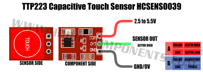
i see that ttp223 only support a Vin of 5v max
so if i have 12v as power supply i think that it will be burn, or i'm wrong?
to filter signal and not having antenna issue it is not enough the capacitor that is installed inside the ttp223?
megamarco833
on 11 Nov 2020
Hi Marco,
I´m back again. As far as I know, ttp223 can operate with power supply from 2 to 5 V, so, taking into consideration that ESP32 GPIO pins operate at a maximum of 3.3V ONLY, you shoud power all ttp223 with 3.3 V, NOT MORE. If you use 12 v, considering the low power consumption of those chips, you can put, just beside ttp223, any cheap analog regulator (12v -> 3.3v) as those based on ams1117 as, for example this (5 piece cost less than 1 €):
https://www.aliexpress.com/item/33035066851.html?spm=a2g0o.detail.1000014.23.324825acMWBe3R&gps-id=pcDetailBottomMoreOtherSeller&scm=1007.13338.189932.0&scm_id=1007.13338.189932.0&scm-url=1007.13338.189932.0&pvid=cb5f778f-e76e-4969-b9ca-2e22c80611d2&_t=gps-id:pcDetailBottomMoreOtherSeller,scm-url:1007.13338.189932.0,pvid:cb5f778f-e76e-4969-b9ca-2e22c80611d2,tpp_buckets:668%230%23131923%2386_668%23808%233772%2381_668%23888%233325%2315_3338%230%23189932%230_3338%233142%239890%233_668%234328%2319927%23278_668%232846%238115%23897_668%232717%237563%23542_668%231000022185%231000066059%230_668%233422%2315392%23458
With respect to the signal wire, try to shield them, maybe inside a coaxial cable, if available. Anyway, test them and you can make an idea if any of the signalare affected by the cables neighbourhood.
Regarding your question about using LAN cables for power supply, I suppose that they are already deployed and you don´t want to deploy aditional cables adecuated for power .... In LAN cables, there are 8 wires and normally are used only wires 1,2,3,6 for LAN so, you could use in parallel 4 and 5 for positive and 7 and 8 for negative. Or if the whole cable is available, use 4 wires for positive and 4 for negative and check. More elegant (and expensive) solution would be to use POE (Power over Ethernet)
But in this case, you need to purchase different power supplys for the equipment.
And If you are using a central power supply and long run cables to provide 5v and 3.3v, you will need a central 12v (to acount for voltage drop in the run), and one regulator just beside the element you intend to power, as TD-er told you. You can use a simple and cheap linear regulator for elements with low power consumption and maybe switching regulators, more eficient, for those drawing more power.
Regards,
Pepe.
plop510
on 14 Nov 2020
Hi Marco,
I´m back again.
hi Pepe, and thanks for coming back, i apreciate so mutch your help!!!!
and i'm sorry if i'm continue to asking but it's all new for me, and i trying to build by myself domotic for my house (or better right now i'm creating some samples with breadboard to be ready to port them in the future in the real house)
As far as I know, ttp223 can operate with power supply from 2 to 5 V, so, taking into consideration that ESP32 GPIO pins operate at a maximum of 3.3V ONLY, you shoud power all ttp223 with 3.3 V, NOT MORE.
but the ESP32 or ESP8266 are working with 5v power supply
and ttp223 is also working with power supply from 2,5 to 5,5v for power supply, and the signal is working with 3,3v
so i want to use the signal of ttp223 with 3,3 gpio from ESPs
If you use 12 v, considering the low power consumption of those chips, you can put, just beside ttp223, any cheap analog regulator (12v -> 3.3v) as those based on ams1117 as, for example this (5 piece cost less than 1 €):
https://www.aliexpress.com/item/33035066851.html?spm=a2g0o.detail.1000014.23.324825acMWBe3R&gps-id=pcDetailBottomMoreOtherSeller&scm=1007.13338.189932.0&scm_id=1007.13338.189932.0&scm-url=1007.13338.189932.0&pvid=cb5f778f-e76e-4969-b9ca-2e22c80611d2&_t=gps-id:pcDetailBottomMoreOtherSeller,scm-url:1007.13338.189932.0,pvid:cb5f778f-e76e-4969-b9ca-2e22c80611d2,tpp_buckets:668%230%23131923%2386_668%23808%233772%2381_668%23888%233325%2315_3338%230%23189932%230_3338%233142%239890%233_668%234328%2319927%23278_668%232846%238115%23897_668%232717%237563%23542_668%231000022185%231000066059%230_668%233422%2315392%23458
so, if i undertand correct your suggestion i will use only one power supply 12V 10A located somewhere in my house, then from this power supply i will start wiring and where i decide to locate my ESP32 or ESP8266 and my 5v arduino relay and PCF8576 i will put a ams1117 that will decrese the 12V to 5V so i can power on my ESPs or my arduino relays.
i see that arduino relays consumes 2.5mA when the relay is in standy and 70mA when the contact is done.
so i think that i must ore one ams1117 to power one 1ESP and 1relay 8ch, nothing more, correct?
the other 8ch relay with ESPs and PCF will require anothe one ams1117 correct?
in this case maybe is it better to use one LM2596 that support more Ampere?
With respect to the signal wire, try to shield them, maybe inside a coaxial cable, if available. Anyway, test them and you can make an idea if any of the signalare affected by the cables neighbourhood.
Regarding your question about using LAN cables for power supply, I suppose that they are already deployed and you don´t want to deploy aditional cables adecuated for power ....
no, i'm planning to renovate my house, so i can choose the best setup.
my idea is to use lan cables because they are "well constructed" and easy to find and they have 8 cables inside so very compact and very good to support gpio connection of 8ch relays....
so my idea is to have some lan cables to wire "normal" internet station and some lan cables to power on domoticz devices like ESPs, relays, PCFs and to distribute signals (relays IN-GPIOs, push buttons TTPs....)
And If you are using a central power supply and long run cables to provide 5v and 3.3v, you will need a central 12v (to acount for voltage drop in the run), and one regulator just beside the element you intend to power, as TD-er told you. You can use a simple and cheap linear regulator for elements with low power consumption and maybe switching regulators, more eficient, for those drawing more power.
now my doubt is about touch buttons that i want to use TTP223
you can imagine that in a house the buttons are dislocated everyhere...so i would like to avoid to have for every push button group (the wall socket for pushbuttons are from 3-4 pushbuttons group) one ams1117 to decrease the voltage...
what could be the best solutions?
Regards,
Pepe.
thanks again!!!
megamarco833
on 14 Nov 2020
Hi Marco,
As far as I know, ttp223 can operate with power supply from 2 to 5 V, so, taking into consideration that ESP32 GPIO pins operate at a maximum of 3.3V ONLY, you shoud power all ttp223 with 3.3 V, NOT MORE.
but the ESP32 or ESP8266 are working with 5v power supply
and ttp223 is also working with power supply from 2,5 to 5,5v for power supply, and the signal is working with 3,3v
so i want to use the signal of ttp223 with 3,3 gpio from ESPs
I want to be clear on this point:
- ESP32 and ESP8266, both work with 3.3 v on all signals, the fact that you can power them with 5V is because in the breakout board there use to be an AMS1117 regulator from 5 to 3.3 v, BUT if you connect any ESP GPIO pin to any chip, the signal voltages should never exceed 3.3v: risk of damaging the ESP. So, in case of TTP223, if you power the chip with 5v, you may get a signal voltage swing exceeding 3.3v (!): beter power TTP223 with 3.3 v.
If you use 12 v, considering the low power consumption of those chips, you can put, just beside ttp223, any cheap analog regulator (12v -> 3.3v) as those based on ams1117 as, for example this (5 piece cost less than 1 €):
https://www.aliexpress.com/item/33035066851.html?spm=a2g0o.detail.1000014.23.324825acMWBe3R&gps-id=pcDetailBottomMoreOtherSeller&scm=1007.13338.189932.0&scm_id=1007.13338.189932.0&scm-url=1007.13338.189932.0&pvid=cb5f778f-e76e-4969-b9ca-2e22c80611d2&_t=gps-id:pcDetailBottomMoreOtherSeller,scm-url:1007.13338.189932.0,pvid:cb5f778f-e76e-4969-b9ca-2e22c80611d2,tpp_buckets:668%230%23131923%2386_668%23808%233772%2381_668%23888%233325%2315_3338%230%23189932%230_3338%233142%239890%233_668%234328%2319927%23278_668%232846%238115%23897_668%232717%237563%23542_668%231000022185%231000066059%230_668%233422%2315392%23458so, if i undertand correct your suggestion i will use only one power supply 12V 10A located somewhere in my house, then from this power supply i will start wiring and where i decide to locate my ESP32 or ESP8266 and my 5v arduino relay and PCF8576 i will put a ams1117 that will decrese the 12V to 5V so i can power on my ESPs or my arduino relays.
i see that arduino relays consumes 2.5mA when the relay is in standy and 70mA when the contact is done.
so i think that i must ore one ams1117 to power one 1ESP and 1relay 8ch, nothing more, correct?
the other 8ch relay with ESPs and PCF will require anothe one ams1117 correct?
in this case maybe is it better to use one LM2596 that support more Ampere?
If you will use only a 12v central power supply and will power all systems from that point, through long run cables (maybe LAN cables), the best option is to use the switching regulator in every endpoint, just beside the element to power, they are more eficient, etc. only in case of an element with a negligible consumption (as TTP223) you can save some money (not much) using a linear type as ams1117 but only "negligible" consumption. As an example: supose that 1117 receive 12v, deliver 3.3v and supports 100ma, as is linear, it will disipate (Vin - Vout) * I = 0,9W and I´d not recommend in this case. So: better use the switching regulator model on all endpoints, and insert an electolitic capacitor at the imput of each regulator to cope with input transients.
With respect to the signal wire, try to shield them, maybe inside a coaxial cable, if available. Anyway, test them and you can make an idea if any of the signalare affected by the cables neighbourhood.
Regarding your question about using LAN cables for power supply, I suppose that they are already deployed and you don´t want to deploy aditional cables adecuated for power ....no, i'm planning to renovate my house, so i can choose the best setup.
my idea is to use lan cables because they are "well constructed" and easy to find and they have 8 cables inside so very compact and very good to support gpio connection of 8ch relays....
so my idea is to have some lan cables to wire "normal" internet station and some lan cables to power on domoticz devices like ESPs, relays, PCFs and to distribute signals (relays IN-GPIOs, push buttons TTPs....)And If you are using a central power supply and long run cables to provide 5v and 3.3v, you will need a central 12v (to acount for voltage drop in the run), and one regulator just beside the element you intend to power, as TD-er told you. You can use a simple and cheap linear regulator for elements with low power consumption and maybe switching regulators, more eficient, for those drawing more power.
now my doubt is about touch buttons that i want to use TTP223
you can imagine that in a house the buttons are dislocated everyhere...so i would like to avoid to have for every push button group (the wall socket for pushbuttons are from 3-4 pushbuttons group) one ams1117 to decrease the voltage...
what could be the best solutions?
You can power 4 pushbuttons with only one 3.3v ams1117. Their consumption is 1.5 micro Amp only. In fact, you can power all of them from a unique ams1117, through the lan cables, as long as you don´t charge the cables with any other load, because with such a low current consumption, thre will not be any voltage drop on the cables but allways remember to put a capacitor on every endpoint to eliminate any transients.
Regards,
Pepe.
plop510
on 14 Nov 2020
If you will use only a 12v central power supply and will power all systems from that point, through long run cables (maybe LAN cables), the best option is to use the switching regulator in every endpoint, just beside the element to power, they are more eficient, etc. only in case of an element with a negligible consumption (as TTP223) you can save some money (not much) using a linear type as ams1117 but only "negligible" consumption. As an example: supose that 1117 receive 12v, deliver 3.3v and supports 100ma, as is linear, it will disipate (Vin - Vout) * I = 0,9W and I´d not recommend in this case. So: better use the switching regulator model on all endpoints, and insert an electolitic capacitor at the imput of each regulator to cope with input transients.
with "switching regulator" you mean the LM2596 ?
not sure to understand correctly where to place the electrolitic capacitor...and what value? 16V 1000uF ?
You can power 4 pushbuttons with only one 3.3v ams1117. Their consumption is 1.5 micro Amp only. In fact, you can power all of them from a unique ams1117, through the lan cables, as long as you don´t charge the cables with any other load, because with such a low current consumption, thre will not be any voltage drop on the cables but allways remember to put a capacitor on every endpoint to eliminate any transients.
but in this case, if i understand correctly, i need to place at every wall socket one ams1117?
inside an house, two floars, there will be around 20 wall sockets (80 push buttons) so i will need 20 ams1117....right?
also here the capacitor should be electrolitic or not? what value? and where i should connect the capacitors?
sorry again for this type of questions :)
now, giving to ESP32 (model with yellow pins) 5,6V as input
https://www.aliexpress.com/item/4001204183286.html?spm=a2g0o.productlist.0.0.22d86445v5lcxx&algo_pvid=df342ee6-0a69-469e-a5fa-344ba61d131c&algo_expid=df342ee6-0a69-469e-a5fa-344ba61d131c-13&btsid=0b0a555e16053800190813677ea515&ws_ab_test=searchweb0_0,searchweb201602_,searchweb201603_
is still working since two days without any capacitors...so it seams that the issue was that 5v was not enought...
just a precisation, all my esp8266 are nodemcu models and the can accept 9v as input voltage (that is what i find)
my ESP32 (nodemcu yellow pins) i see that are marked as 5V so i guess that the can accept 5v as power input
my ESP32 (nodemcu black pins) i see that are marked as Vin (not 5V in this case)...what's the max voltage input for this model?
thanks!
megamarco833
on 14 Nov 2020
Hi Marco,
_with "switching regulator" you mean the LM2596 ?
not sure to understand correctly where to place the electrolitic capacitor...and what value? 16V 1000uF ?_
Yes, there are many breakout boards with that chip and it shows a good performance.
If you have a 12v central supply, and a long run lan cable to reach a switching regulator that will provide 5v power to an ESP, the cap should be connected just at the input of the switching regulator. The voltage rating of capacitor should be a bit bigger, maybe around 20v. Capacity: 470 o 1000 uF will do the job and also, to avoid fast spikes, in parallel, a ceramic o similar of 100k pf.
_but in this case, if i understand correctly, i need to place at every wall socket one ams1117?
inside an house, two floars, there will be around 20 wall sockets (80 push buttons) so i will need 20 ams1117....right?
also here the capacitor should be electrolitic or not? what value? and where i should connect the capacitors?
sorry again for this type of questions :)_
The pushbottoms have a so low power consumption that yoy can power all of them (to 3.3v!) using a central regulator (from the 12v central supply). So, you´ll have your central 12v supply, and just connected to it a 3.3 regulatos (that can be the same LM2596, regulated to 3.3v) and then the long run lan cables that will connect to each pushbuton. So, you only need 1 regulator. The reason is the low power consumption than ensures that all pushbuton grouped consumption will not reach 0.5 milli Amps and there will not be any voltage dropout through the cables. The only remendations shoud be:
- to include on each pushbuton group an small capacitor of just several uF and
- do not use the 3.3 v supply to power any other device that might be more power hungry.
So, at the end you will have a central supply providing 12v and 3.3v.
_just a precisation, all my esp8266 are nodemcu models and the can accept 9v as input voltage (that is what i find)
my ESP32 (nodemcu yellow pins) i see that are marked as 5V so i guess that the can accept 5v as power input
my ESP32 (nodemcu black pins) i see that are marked as Vin (not 5V in this case)...what's the max voltage input for this model?_
I don´t know all ES32 on the market but having a look to schematics, they have an internal regulator with an 1117 to provide the needed 3.3v. This regulator can accept 12v. The external 5V input is only connected to the regulator and to the USB power signal, but with a diode to prevent reverse current flow to the USB connector. So I thing they could accept 9v also.
I attach the schematic.
Regards,
Pepe.

plop510
on 18 Nov 2020
Hi Marco,
hi Pepe, here what i understand, sorry for very bad schematic like a 6 years old child :) (not want to be offensive for 6years old child :) :-) )

i set an example with two espXX located far from the power supply, and close to them the switching regulator.
if i understand correctly i will place at the output of LM2596 1 capacitor 20V 460uF and 1 capacitor ceramic 100k pf.
correct?
then i have two push button TTP223, in this case, TTP223 is far from power supply and the regulator to power them at 3,3v is located close to 12v power supply.
every group of TTP223 need a capactitor? (in this example the group are two: button1 and button2)
anyway i though that TTP223 has already on board, i'm wrong?
thanks!
megamarco833
on 2 Dec 2020
Related issues
 Oxyandy
·
180Comments
Oxyandy
·
180Comments
 ferazambuja
·
129Comments
ferazambuja
·
129Comments
 Erd86
·
90Comments
Erd86
·
90Comments
 Budman1758
·
83Comments
Budman1758
·
83Comments
 TheAppService
·
105Comments
TheAppService
·
105Comments
Most helpful comment
Hi, thanks for the info.
But if i do not understand well, if the GND pin close to Vin pin are marked wrong, if i need to power on this esp32 where i connect vin and gnd?
I guess vin (+5v) is correct pin, so i will put here 5v
But for gnd there is only another one pin marked as gnd: close to 3v3, i need to use this one?
Do you know if maybe there is another pin that it is gnd not marked?
Thanks