Espeasy: Pulse counter - problem still exists?
The issue #1673 describes the change from SENSOR_TYPE_SINGLE to SENSOR_TYPE_SWITCH, which was done by pull #1780.
But the sourcecode still contains following lines:
35 Device[++deviceCount].Number = PLUGIN_ID_003;
36 Device[deviceCount].Type = DEVICE_TYPE_SINGLE;
37 Device[deviceCount].VType = SENSOR_TYPE_SINGLE;
Sorry for my maybe stupid question, but what about the chage? I have a problem with a Wemos mini and a TCRT5000 sensor to set apart between the falling and rising flank.
Thank you.
 Parodontitis
All 42 comments
A few months ago we had made some changes regarding P001, P009 and P019.
These are the switch and 2 GPIO expanders.
In essence the switch plugin is also some kind of GPIO handler, but then for the internal GPIO pins.
There have been quite a few changes, but they got reverted and put aside to deal with later, since these changes had all kind of side effects with rules no longer working like before.
One of the suggested changes (not sure if they are still active now, due to the reverting part) was to use the code of P003 also in P001 to handle debounce events etc. But like I said, I don't know right now what the current state is.
The Pull request you are pointing to is about the expanders and in this issue you're talking about P003.
Another thing to try (and you should know about)... The plugins that need to assign an interrupt to a GPIO pin should only be in one of the first 4 spots for plugins (in the table of selected plugins on the device page)
If you have the plugin in a later position, please move it up to one of the first 4 spots.
 TD-er
on 28 Feb 2019
TD-er
on 28 Feb 2019
Hi all,
debounce is working for plugins P001 (GPIO), P009 (MCP) and P019 (PCF).
Please report if there are issues with the debounce feature.
 giig1967g
on 28 Feb 2019
giig1967g
on 28 Feb 2019
Thank you for this information. What would you recommend to me to find a way for a work around my problem with the correct distinction of the flank? Regardless of the setting of the "mode type" ("RISING", "FALLING" or "CHANGE") every change will be registered. For the correct function of my circuit I only need to register either RISING or FALLING not both types.
I use the first task in plugin, regarding to the this documantation. "Only task number 1..4 is currently supported for the pulse plugin!"
Parodontitis
on 28 Feb 2019
The interrupt mode of P003 is something I haven't looked into.
Will need to check
giig1967g
on 28 Feb 2019
I have a similar problem. After some successful counts on the FALLING edge, the counter suddenly began to count the signal CHANGES. The FALLING setting was still displayed correctly in the Web UI. If I switch the trigger from FALLING to RISING, it started counting the RISING edges. But again a a few minutes later it switches back to counting the signal CHANGES again. Very strage, I will have to do some further investigation on this.
 oerweber
on 11 Mar 2019
oerweber
on 11 Mar 2019
does it work ok after restart?
 uzi18
on 11 Mar 2019
uzi18
on 11 Mar 2019
What other plugins do you have active?
TD-er
on 11 Mar 2019
The Pulse Counter is the only active plugin.
I will do more testing using the most current development version and on a different hardware, just to be sure that there is no hardware issue.
oerweber
on 11 Mar 2019
Like me. The pulse counter is the only one active plugin.
Parodontitis
on 11 Mar 2019
I did some further testing yesterday.
First cognition: When feeding the GPIO with a rectangular signal from a function generator, everything is fine. Rising, Falling, change: Works perfekt.
The problem occured, when I connected a sensor (in my example a TCRT5000 IR module) to the GPIO. This kind of sensor produces sporadically a bounced signal. Depending on which and how a object is moved in front of the sensor.
I try to visualize:
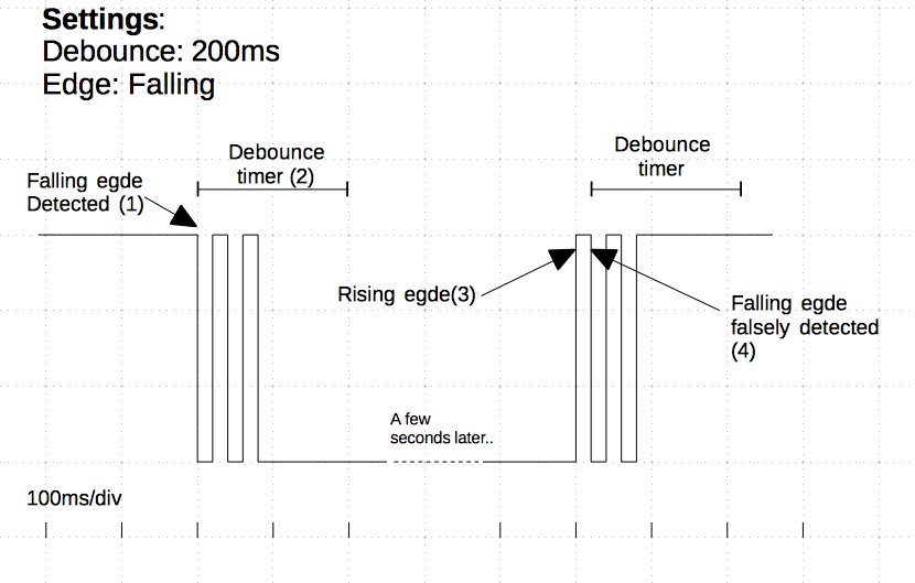
The detection of the first falling edge works(1) as expected. The following bounces are ignored by the debounce algorithm(2). But, when some seconds later, the signal raises back to high level (3) and bounces again, this bounce is detected falsely as valid falling edge (4).
In the plugin, the interrupts are only tiggered at the falling edges. Therefore the ISR handler cannot determine the difference between a valid falling edge (1) and a bounced falling edge (4). It sees no diffference if there was a immediatel rising edge before (when bouncing) or the signal was long time high level.
Same applies to rising edges vice-versa.
This is also the reason why only the CHANGE setting works reliable. Then using the CHANGE setting, the interrupt is triggered on _every_ edge and the debounce algorithm works as expected.
I hope I have explained that in my not so perfect English reasonably understandable ;-)
I see two possible solutions for this:
a)
Trigger the ISR on every signal change no matter whats configured. And then sort out in the ISR handler which edges are really wanted and apply the debounce timer accordingly.
b)
Earlier, in 8 bit controller times one used a timer interrupt to sample the IO pin in regular intervals. If the same value was sampled some times in order, the edge was declared as 'detected'. This was a very reliable and less resource using approach.
A popular solution for this is from Peter, found here: https://www.mikrocontroller.net/attachment/highlight/1927 It can easily and reliably recognize and distinguish the desired edges.
So, thats all for now. If I will find some time, I will try some further experiments on this issue.
oerweber
on 12 Mar 2019
As far as I know the algorithm used, it just ignores the next pulses during the set 'debounce time'.
So maybe it is just the algorithm that's not working like one would expect.
I agree with you that it makes sense to expect it to only accept a pulse if it was high (or low?) for at least the debounce time. But to me it looks like it is now only working like this for "post-debounces" and not for "pre-debounces" and those also appear ofcourse. (maybe even more often)
TD-er
on 12 Mar 2019
This is what i mean with solution a). If the ISR would be triggerd on _every_ edge, it would be able to determine also the post-debounces. The ISR could increase the counter only on the falling edges and use the rising edges only for resetting the debounce timer.
oerweber
on 12 Mar 2019
After a few more thoughts I came to the conclusion that the timer based solution will be the only one, which will relieable work for FALLING or RISING edges on bounced signals. I created my own plugin which works flawless since a few days now. If one is interested, you can find it here: https://github.com/oerweber/ESPEasyPluginPlayground/blob/master/_P222_DebouncedCounter.ino
oerweber
on 18 Mar 2019
I've seen the PR on that one and indeed it will certainly be used as inspiration here ;)
Thanks.
TD-er
on 18 Mar 2019
Please write in documentation what debounce time means really (I did not find any single comment about it).
If I understand it properly (and as mentioned above), "it ignores all NEXT pulses during the 'debounce time' period".
It would be great to have an option to set glitch filter as implemented in the pigpio Python library.
(Level changes on the GPIO are not reported unless the level has been stable for at least steady microseconds. The level is then reported. Level changes of less than steady microseconds are ignored.)
 PetrJakes
on 2 Apr 2020
PetrJakes
on 2 Apr 2020
i like to test this P222 debounced counter myself but am not as eperienced with the arduino software to compile it myself. is P222 in the current test_beta version.
 GravityRZ
on 5 Apr 2020
GravityRZ
on 5 Apr 2020
Please write in documentation what debounce time means really (I did not find any single comment about it).
done ;-) pushed to https://github.com/oerweber/ESPEasyPluginPlayground/blob/master/_P222_DebouncedCounter.ino
It would be great to have an option to set glitch filter as implemented in the pigpio Python library.
(Level changes on the GPIO are not reported unless the level has been stable for at least steady microseconds. The level is then reported. Level changes of less than steady microseconds are ignored.)
This is not necessary, the timer based debounce algorhythm of this plugin does this automatically. Using a "wait for some time to get a stable signal" (glitch) approach does not work reliable. See timing diagram above.
oerweber
on 6 Apr 2020
It is always better to add hardware filter for signal like RC, sometimes double Schmitt inverter
uzi18
on 6 Apr 2020
It is always better to add hardware filter for signal like RC, sometimes double Schmitt inverter
This discussion is old. Maybe older than I'am. It may be true for you and your application but not generally. Software debouncing can be done down to the slowest 8bit controllers and it only costs are few clock cycles in timer interrupt. If you have to debounce more than one signal you will end up with a lot of extra hardware when choosing the hardware approch. My preferred code example (https://www.mikrocontroller.net/attachment/highlight/1927) can debounce one complete IO port with its 8 lines at one time.
oerweber
on 6 Apr 2020
I was thinking to add the description of debounce time somewhere in "general documentation" of ESPEasy.
Anyway, debouncing does not help in the situation, when there are some glitches/spikes/interferences on the input signal line. Only glitch filter can solve this.
I am not sure about additional hardware filters.
ESP8266 does not have enough computing power to implement something similar as a "glitch filter" implemented in the pigpio Python library???
PetrJakes
on 6 Apr 2020
ESP8266 does not have enough computing power to implement something similar as a "glitch filter" implemented in the pigpio Python library???
Well, that's a question that may be hard to answer.
One thing for sure is that ESPEasy is not a real-time application and the ESP8266 lacks proper HW interrupts for registering very short glitches.
So it may very well be that a simple 8-bit microcontroller with much less resources can handle glitches better than ESPEasy running on the much more powerful ESP8266 can do.
TD-er
on 6 Apr 2020
One thing for sure is that ESPEasy is not a real-time application and the ESP8266 lacks proper HW interrupts for registering very short glitches.
So it may very well be that a simple 8-bit microcontroller with much less resources can handle glitches better than ESPEasy running on the much more powerful ESP8266 can do.OK, now I understand it much better.
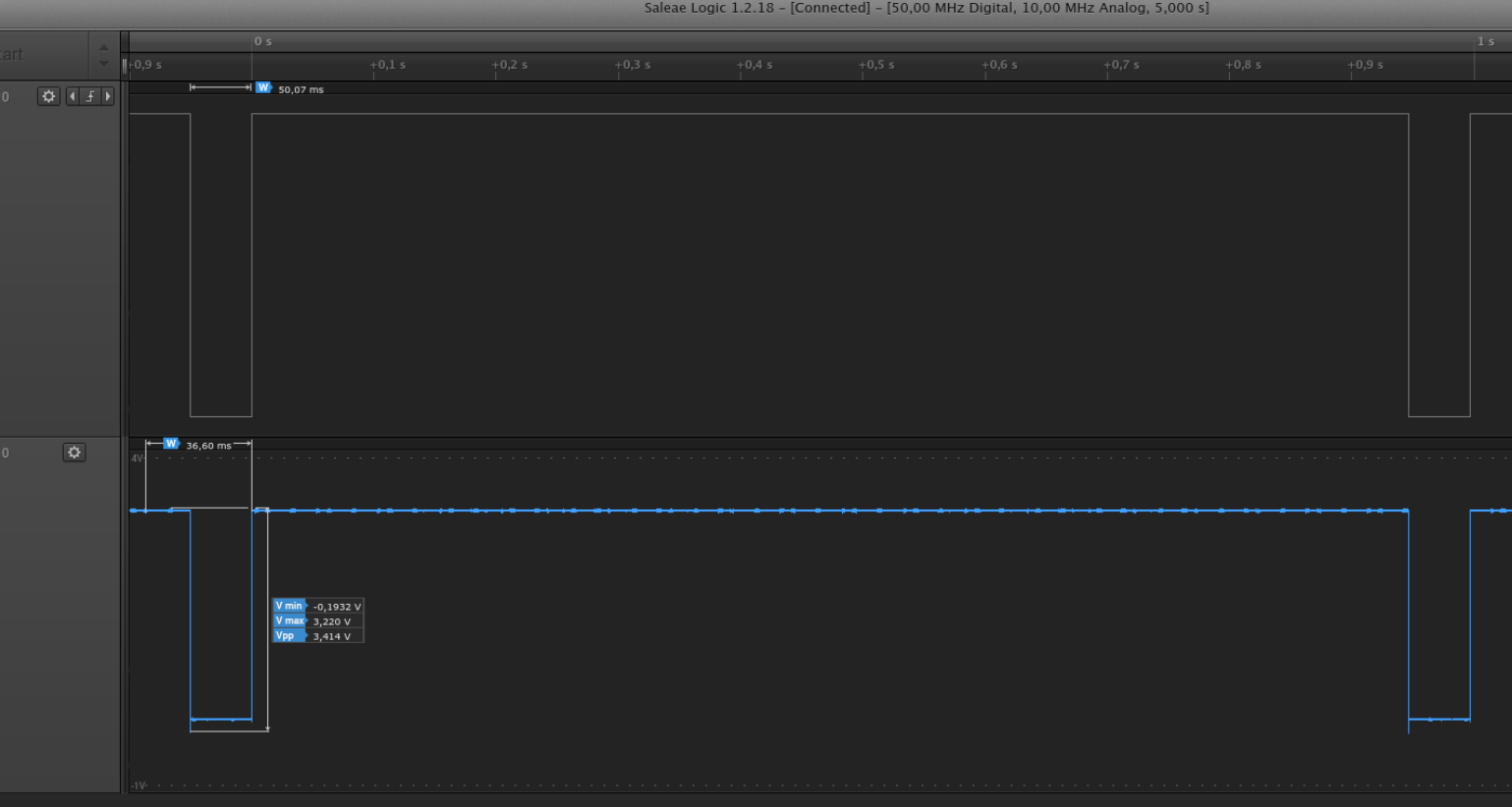
Anyway, I was trying to implement ESPEasy as a counter for 10 water meters (very clean output signals, professional open collector HW interface, grounding GPIO for 50ms - recorded signal in the attachment).
Result of the long term recording: many signal pulses were not recognized/recorded by an ESPEasy (I was comparing recorded pulses to the water meter gauge/odometer).
I understand the counter records in ESPEasy are not persistent. I was sending data to mqtt so lost of data because of proceeding restarts of an ESPEasy can not be the reason for missing signals.
PetrJakes
on 6 Apr 2020
I understand the counter records in ESPEasy are not persistent. I was sending data to mqtt so lost of data because of proceeding restarts of an ESPEasy can not be the reason for missing signals.
In the latest code it is persistent during warm reboots.
If the pulses are clean (meaning no de-bounce needed) and the width is very short compared to the pulse interval, then you can consider adding a flipflop circuit.
A flipflop will change every time it registers a pulse, so effectively halving the frequency.
Meaning the pulse counter should then count on every change to keep the same count interpretation.
Such a circuit does eliminate the realtime processing needed on the ESP as the output state of the flipflop remains the same for as long as the pulse interval and thus much less chance of missing a pulse on the ESP.
TD-er
on 6 Apr 2020
We can think about support for external counters maybe they are available for spi/i2c?
Or as external uC like arduino nano/mini/pro?
uzi18
on 6 Apr 2020
Such a circuit does eliminate the realtime processing needed on the ESP as the output state of the flipflop remains the same for as long as the pulse interval and thus much less chance of missing a pulse on the ESP.
Not sure if I understand well your reply.
AFIK, the input set as a counter in the ESPEasy, is set as pulled-up (the setting is in the source code, not in the web interface), and counter is counting falling edges only.
Not sure if flip-flop circuit can be used here.
PetrJakes
on 6 Apr 2020
Not sure if flip-flop circuit can be used here.
A 'falling edge' also has to come up again :)
Worst case scenario is that you will be the length of the "low time" behind.
You can always invert the input signal using a transistor.
And if you need to add a flipflop to your circuit, you may also add a pull-up resistor if needed.
If the flipflop actively pulls the level down and up on the output, you don't need to enable the pull-up resistor in the ESP.
TD-er
on 6 Apr 2020
If the flipflop actively pulls the level down and up on the output, you don't need to enable the pull-up resistor in the ESP.
There is a pull-up set by default in the _P003_Pulse.ino if you are using the input as a counter.
pinMode(Settings.TaskDevicePin1[event->TaskIndex], INPUT_PULLUP);
Maybe you can add the option in to the user interface to set/define the pull-up resistor (PUD_OFF, PUD_UP, PUD_DOWN)
You can always invert the input signal using a transistor.
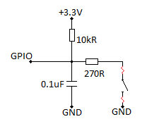
And if you need to add a flipflop to your circuit, you may also add a pull-up resistor if needed.Additional circuit complicates the application. I was expecting to connect the GPIO directly to the water meter open drain (possibly to add a 100nF capacitor - see attached schematic).
If I understand it properly now, the ESPEasy counter is not interrupt driven and can miss some input signals.
 PetrJakes
on 6 Apr 2020
PetrJakes
on 6 Apr 2020
If I understand it properly now, the ESPEasy counter is not interrupt driven and can miss some input signals.
That's correct.
The processing of pulses is done in software, so it can miss a count.
ESP32 does have hardware interrupt, but right now we do not (yet) use that functionality.
But future updates will implement support for it.
TD-er
on 6 Apr 2020
i currently use an optocoupler. this creates a clear seperation between the 3.3v(5v in picture) logic from the nodemcu and the 5v/12v logic from the proximity sensor. Way better then any resistor divider. i think we do not need a hardware interrupt, we need an event interrupt(which is hardware based but needs to be supported by software).

GravityRZ
on 7 Apr 2020
The way it now works is as follows:
- ISR callback function assigned to pin state change
- ISR callback function marks a flag to notify a change (count++ etc)
loop()processes these flags
As the ESP82xx does not have HW interrupts, I assume this is handled in the core library. (= software)
So if the core lib itself is busy in blocking code, or our own software, for X msec.
Then it may miss any state change present for less than this X msec.
This is why I suggested to use a flipflop, to convert a very short pulse (and long wait for next pulse) into a state which keeps the same state for as long as the duration between 2 pulses.
Maybe you can place a small capacitor over pin D...13 in your schematic? Although I don't know if that will cause a current through the transistor of the optocoupler which may damage it. A small resistor between the cap and the transistor may protect the transistor.
The idea is to discharge the capacitor quickly (via transistor) and charge it slowly (via 10k) so the pulse is stretched a bit more.
TD-er
on 7 Apr 2020
i currently use an optocoupler. this creates a clear seperation between the 3.3v(5v in picture) logic from the nodemcu and the 5v/12v logic from the proximity sensor. Way better then any resistor divider. i think we do not need a hardware interrupt, we need an event interrupt(which is hardware based but needs to be supported by software).
Optocoupler GravityRZ mentioned is doing voltage logic shifting and electric separation of the input line signal and GPIO only.
Optocoupler can not help to make better detection of the short signals on the GPIO input (I am trying to detect signals 50ms -see the print-screen in my post above - many of them are not detected).
The only way to solve this is to add a flip flop to make short signals longer (as TD-er is recommending).
Or we have to wait for the release of the ESPeasy for ESP32, with the support for HW interrupts.
PetrJakes
on 7 Apr 2020
yes, that is always a good idea to do .
however i think the capacitor need to be bigger(around 50uF to get a 0.5 second stretch or am i calculating it wrong). will do some testing on a spare esp ti see what the ideal value should be
currently the ESP is shrinkwrapped so difficult to adjust.
i did something else to create the same result.
i added a small magnet on the side of the proximity sensor.
as a result the pulse now is much wider because the sensor is more sensitive.
ofcourse i can still get additional pulses/jitter when i am on the border of the sensitivity but sofar 3 days up and running without either missing or extra pulses.
looking at the duty cycly it is now +/- 40% where it was around 5% in the beginning.
what a small magnet is good for :-)
regarding the p222 counter. it is totally buggy and can not be used for this purpose
GravityRZ
on 7 Apr 2020
i currently use an optocoupler. this creates a clear seperation between the 3.3v(5v in picture) logic from the nodemcu and the 5v/12v logic from the proximity sensor. Way better then any resistor divider. i think we do not need a hardware interrupt, we need an event interrupt(which is hardware based but needs to be supported by software).
Optocoupler GravityRZ mentioned is doing voltage logic shifting and electric separation of the input line signal and GPIO only.
Optocoupler can not help to make better detection of the short signals on the GPIO input (I am trying to detect signals 50ms -see the print-screen in my post above - many of them are not detected).
The only way to solve this is to add a flip flop to make short signals longer (as TD-er is recommending).
Or we have to wait for the release of the ESPeasy for ESP32, with the support for HW interrupts.
you are right but the optocoupleer helps with other things.
could we not solve this real easy by just using a second debounce timer for rising signals.
this way we can select falling, rising, changing signals and can also create our own duty cycle
GravityRZ
on 7 Apr 2020
just tested it with a 100uf elco and a 220uf elco
if i set debounce to 500ms and falling
I pull D5 low and a pulse it counted. then when the elco gets charged again a pulse
how can this be because the voltage is rising, not falling.
tested again. as long as i keep D5 pulled to low the is 1 pulse counted. when i release and the voltage gets higher i get another pulse
rising works as expected but falling acts the same as CHANGE.
please note this behaviour is without the elco on D5
GravityRZ
on 7 Apr 2020
can you post schematic and oscilloscope / analyser print screen?
PetrJakes
on 7 Apr 2020
no i do not have it but i figured out what is causing this
with debounce on 0 falling works(eg 1 pulse, also when released after 2 seconds)
with debounce set to 2000 you get 1 pulse when falling(D5 to ground) and again 1 pulse if you release it after 2000ms. when released within the debounce time it counts as one.
GravityRZ
on 7 Apr 2020
Without the schematic, scope print screen or a signal diagram and description (see above in this thread to the (oerweber commented on Mar 12, 2019) it is hard to comment describe whats going on.
PetrJakes
on 7 Apr 2020
well it is a really simple setup
nodemcu8266
espeasy mega20200328(also tried others)
switch connected to D5 and ground
i have this in a test setup to see what happens to the pulsecounter plugin.

pulsecounter
debounce 2000ms
falling
Test1
switch closing(pulling D5 to ground)
result pulse is counted
Correct behaviour
switch opening within 2000ms of closing
result no pulse is counted
Correct behaviour
Test2
switch closing(pulling D5 to ground)
result pulse is counted
Correct behaviour
switch opening AFTER 2000ms of closing
result pulse is counted
NOT CORRECT behaviour
this pulse is rising so it should not be counted
tested the same but now plugin set to rising
Test3
switch closing(pulling D5 to ground)
result no pulse is counted
Correct behaviour
switch opening within 2000ms of closing
result pulse is counted
Correct behaviour
Test4
switch closing(pulling D5 to ground)
result no pulse is counted
Correct behaviour
switch opening AFTER 2000ms of closing
result pulse is counted
Correct behaviour
GravityRZ
on 8 Apr 2020
Your tests are an "alchemy" :D
without logical analyser/oscilloscope you can not have relevant results/conclusions.
Test2
switch closing(pulling D5 to ground)
result pulse is counted
Correct behaviour
switch opening AFTER 2000ms of closing
result pulse is counted
NOT CORRECT behaviour
this pulse is rising so it should not be countedAbove you are not correct. The switch spring is bouncing probably when you are opening it. This is producing some falling edges as well. So the counter is counting this pulse.
But again. You need and analyser/oscilloscope to get correct results.
HTH
PetrJakes
on 8 Apr 2020
of course you are right (but i do not have a scope)
tried something else. i hooked up a micro switch(those small click types)
With that switch i indeed do not see the double count.
So my error, without the switch debounce i used several elco's to see if it can be used as a debounce.
with the switch i have a single count. when adding an elco across the switch it creates a second count when the voltage is rising. so the esp is very sensitive for jitter.
even an elco discarged and charges again is causing a jitter in the uprising pulse.
conclusion(for me) an elco on the output when drawn to gnd will actually make the problem bigger
it perhaps will keep he input longer to the ground(extending the pulselenght) but the rise in voltage is somehow not free of spikes
GravityRZ
on 8 Apr 2020
I would like to recommend to you to stop doing an "alchemy" :D
There is a lot of sources on the internet to study... :D
https://www.electronics-tutorials.ws/rc/rc-integrator.html
https://www.electronics-tutorials.ws/rc/rc_3.html
.......
GOOD LUCK
PetrJakes
on 8 Apr 2020
thanks, i know al that stuff but will refrain myself until i have solid data
GravityRZ
on 8 Apr 2020
Related issues
 tedenda
·
6Comments
tedenda
·
6Comments
 jroux1
·
6Comments
TD-er
·
3Comments
jroux1
·
6Comments
TD-er
·
3Comments
 hamed-ta
·
5Comments
TD-er
·
4Comments
hamed-ta
·
5Comments
TD-er
·
4Comments
Most helpful comment
After a few more thoughts I came to the conclusion that the timer based solution will be the only one, which will relieable work for FALLING or RISING edges on bounced signals. I created my own plugin which works flawless since a few days now. If one is interested, you can find it here: https://github.com/oerweber/ESPEasyPluginPlayground/blob/master/_P222_DebouncedCounter.ino