Espeasy: Device Switch Input does not reflect GPIO status change - not working from mega-20181130
Checklist
- [x] The title of this issue is "to the point" and descriptive.
- [x] This issue describes what is happening.
- [ ] This issue describes what components are affected (e.g. name of plugin/controller)
- [x] This issue describes how to reproduce it.
- [x] This issue describes when it was introduced (when known) and what version is now showing the problem.
I have...
- [x] searched the issue tracker or the forum for a similar issue. (include links when applicable)
- [x] entered a system description using "Copy info to clipboard" on the sysinfo page. (when possible)
- [x] entered the full filename of the used version (e.g.
ESP_Easy_mega-20181001_test_ESP8266_4096_VCC.bin) - [x] given a list of active plugins or controllers when applicable.
- [ ] filled out all applicable fields below.
Steps already tried...
- [ ] Tried a clean install (empty
.binfiles are included in the ZIP) - [x] Tested previous/other build (mention which one already tested)
- [ ] Tested on other node to make sure hardware isn't defective.
- [x] Verified if the problem is limited to a single plugin/controller
Summarize of the problem/feature request
When pin state is changed using gpio command the Switch Plugin connected to same GPIO as Normal Switch does not reflect the change and taskvalue remains same. Functionality well in version ESP_Easy_mega-20181129 but stop working in ESP_Easy_mega-20181130.
Expected behavior
When command gpio,0,1 is used the taskvalue should be changed as well.
Actual behavior
The task value remains same
Steps to reproduce
- Use Device Switch Input and configure it to gpio-1
- Use following rules which should toggle gpio output
System configuration
Hardware:
ESP8266-01 with 4MB flash
ESP Easy version:
ESP_Easy_mega-20181130_test_ESP8266_4096_VCC
ESP Easy | Information |
-----|-----|
Build:⋄|20103 - Mega|
Libraries:⋄|ESP82xx Core 2_4_2, NONOS SDK 2.2.1(cfd48f3), LWIP: 2.0.3 PUYA support|
GIT version:⋄|mega-20181130|
Plugins:⋄|73 [Normal] [Testing]|
Build time:⋄|Nov 30 2018 03:16:50|
Binary filename:⋄|ESP_Easy_mega-20181130_test_ESP8266_4096_VCC.bin|
Rules or log data
//what to do just after boot
On System#Boot Do
  TimerSet,1,5
  gpio,0,1
Endon

On Rules#Timer=1 Do
  if [Light#Relay]=1.00
    gpio,0,0
  else
    gpio,0,1
  endif
  TimerSet,1,5
Endon
 kristi5
All 111 comments
Very likely related to this PR: https://github.com/letscontrolit/ESPEasy/pull/2057
Hopefully @giig1967g can shed some light on this?
 TD-er
on 30 Nov 2018
TD-er
on 30 Nov 2018
will look into it.
For the moment try this:
On Rules#Timer=1 Do
  gpioToggle,0
  TimerSet,1,5
Endon
 giig1967g
on 30 Nov 2018
giig1967g
on 30 Nov 2018
Found the reason:
if you create a taskdevice for GPIO, this is assumed to be an input PIN (a switch).
Therefore now it's not possible to change it's status using GPIO command.
Probably previously it was possible. Logically it's a mistake, but I can see that maybe many have used this backdoor to define an outpin in the device page.
So, it's more a question if we should allow an INPUT pin to be set with the GPIO command and then if this PIN should become an then an OUTPUT pin.
What I can do for now is to allow the GPIO command to modify also INPUT pins.
@TD-er what do you think?
giig1967g
on 1 Dec 2018
Hmm this one is tricky.
You should not set the GPIO pin if it is an input, but only the state of the connected switch plugin.
And only this should be done when the switch is a toggle switch, or something for which the current state of the GPIO pin cannot cause a conflict.
For example:
- Toggle (only state change of GPIO triggers a state change of the switch)
- Dimmer??? Time pressed may set a new dimmer value, I assume.
- Long-press/double-click
Things that should not be allowed:
- (input) Switch in "normal" state (or inversed "normal") must always match the GPIO input, so cannot be overruled.
This once more indicates the current switch plugin has way too many functions and should be split.
TD-er
on 1 Dec 2018
Agreed.
But what should we do with all legacy rules that were using this backdoor?
Allow or clearly state that starting ffrom 30/11 it's forbidden?
giig1967g
on 1 Dec 2018
Let's set the date of this decree to December 1st ;)
"Thou shall not violate logic"
We could allow it for now and split the switch plugin, so all rules must be altered.
You should have a switch input and a switch output, or at least it should be really well defined in the plugin config.
Like it is now, it will remain buggy.
TD-er
on 1 Dec 2018
I don't think any rule (or software) should be allowed to override a mechanical switch. If this breaks previous precedent then so be it. Just because you can do something does not mean you should. This is after all the development branch and as such functionality changes. That's just part of the process. Trying to get around that just causes more problems than it solves IMHO.
Just my 2 cents worth.... :)
 Budman1758
on 1 Dec 2018
Budman1758
on 1 Dec 2018
In this example the plugin Switch Input was used for output pin connected to relay. I agree that its weird but the purpose is not override a mechanical switch. The purpose of usage plugin in this scenario (not only gpio commands):
- be able to read the actual status of relay and make some IF/ELSE decisions in Rules
- send actual value of relay via MQTT (Open HAB MQTT controller used) whenever the state change
The proposed solution to split plugin Switch Input and have some Switch Output seems to be good approach.
Or did i miss some possibility to configure Switch Input plugin for output pins already now?
kristi5
on 1 Dec 2018
- be able to read the actual status of relay and make some IF/ELSE decisions in Rules
If I'm not mistaken there are new commands already that can give GPIO status. I don't believe they have been documented yet.
Perhaps @giig1967g could shed some light....?
Budman1758
on 1 Dec 2018
You can always read the state output of a switch plugin
TD-er
on 1 Dec 2018
You could use [PLUGIN#GPIO#PINSTATE#number] or [PLUGIN#PCF#PINSTATE#number] or [PLUGIN#MCP#PINSTATE#number] to read the state of a PIN to be used in a "if/then/else" statement.
Or you can use "monitor,gpio,x" to create an event when a PIN has changed.
Finally, the OP was using the above workaround to create a toggle logic.
Today there is the gpioToggle command that does the job in one single line of code without the need to create a task in the device list.
giig1967g
on 1 Dec 2018
before it was like gpio, 0,0 sets gpio0 to output 0, then 0, 1 sets output to 1, and 0,2 sets as input, especially for pcfgpio
so gpio commands should change input into output, and/or add one option to set it in explicitly in task
 uzi18
on 1 Dec 2018
uzi18
on 1 Dec 2018
So I think we all agree to break some rules to follow the rules of logic ;)
TD-er
on 1 Dec 2018
haha and the dreams come true :)
in my opinion shoud be type of gpio (input/output) and monitor available as task configuration
uzi18
on 1 Dec 2018
I have left the command
gpio,x,2 to define an input pin from rules.
giig1967g
on 1 Dec 2018
but does gpio command change gpio to output?
uzi18
on 1 Dec 2018
The new commands gpioToggle or monitor,gpio solves the problem of toggling output pretty well.
The PLUGIN#GPIO#PINSTATE#number solves if/then/else tests as well.
How to solve the behavior which was there in version mega-20181129 when gpio output pin state was changed using gpio commands then attached Device switch follows the pin change and respectively update the device value and send new value to controller. In case of OpenHub MQTT the new value was automatically published to mqtt broker. Will this functionality available in new Device Switch Output later? Any temporary solution how to publish actual value of pin to MQTT broker?
kristi5
on 1 Dec 2018
but does gpio command change gpio to output?
Command GPIO:
it changes to OUTPUT if gpio,x,1 or gpio,x,0
it changes to INPUT if gpio,x,2
It was already like that. I didn't change the logic.
giig1967g
on 1 Dec 2018
@kristi5
you can use monitor command:
It generates an event when thr GPIO changes status and the GPIO is not in the devices list.
Or you can use the Publish command.
giig1967g
on 1 Dec 2018
i use monitor,gpio,0 and then i am using gpio,0,1 or gpio,0,0 commands but no event is generated.
kristi5
on 1 Dec 2018
Hi,
the original monitor command would return an event if a pin change status except when changed by a command. The reason behind it is because the idea is to monitor asynch events or in other words, to work as a interrupt. So, if you send a gpio command, you don't need an event as you already know that that event is going to fire and you could send all the other commands at the same time.
On the other hand, I think it could be useful to send the monitor event also for when initiated by a command (expecially if started from an a MQTT or HTTP command).
I will made a PR this.
giig1967g
on 2 Dec 2018
I have now something similar on my test Sonoff POW.
I use the "Factory reset" generated plugins and rules and that doesn't work anymore.
So I need to know what to change, since this is something others will experience too.
The "Button"

The Relay: (I already disabled the "Internal PullUp")
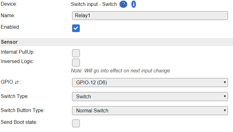
The generated rule:
on Button1#switch do
  if [Button1#switch]=1
    gpio,12,1
  else
    gpio,12,0
  endif
endon
The pin is used for relay so its output. The only way to change pin state is via gpio command so there is no other async event except those where command may come via MQTT /cmd topic or http://
There is also following note in documentation https://espeasy.readthedocs.io/en/latest/Plugin/P000_Relay.html#setup And according to it it should be possible to monitor gpio output pins (e.g. for relays). Is it not valid doc from mega-20181130?
   Note

   If you want to monitor and have the GPIO state published you do this by adding as a Switch Input -
   Switch , it will not be a switch per say but you will get the state published automatically.
@kristi5 The docs should also be updated, along with pull-requests.
For now, the ReadTheDocs content is mainly a copy/collect of the information stored on the wiki, so regarding the switch plugin, it is already outdated, since this was changed very recently.
TD-er
on 2 Dec 2018
@TD-er
remove Relay1 from the task list and it wil work.
You have declared Relay1 as an input when actually it's an output.
giig1967g
on 2 Dec 2018
Maybe there is also a parse issue?
30976704: EVENT: Clock#Time=Sun,10:36
30981553: SW : GPIO=0 State=0 Output value=1
30981561: EVENT: Button1#Switch=1.00
30981577: ACT : gpio,12,1
30981579: SW : GPIO 12 Set to 121
30987753: SW : GPIO=0 State=0 Output value=0
30987756: EVENT: Button1#Switch=0.00
30987779: ACT : gpio,12,0
30987781: SW : GPIO 12 Set to 120
30987793: SW : GPIO=12 State=1 Output value=1
30987800: EVENT: Relay1#Switch=1.00
SW : GPIO 12 Set to 120
This is printed by this line:
log = String(F("SW : GPIO ")) + String(event->Par1) + String(F(" Set to ")) + String(event->Par2);
@TD-er
I think a it's a log issue. But will check immediately.
giig1967g
on 2 Dec 2018
@giig1967g Remember, I am working from the branch with the stack reduce/new rules PR
So it could be a "new" bug, related to my changes.
TD-er
on 2 Dec 2018
I suspect it has something to do with your changes as in release 20181130 the message is correct, while in your latest testing build the message is wrong.
giig1967g
on 2 Dec 2018
OK, then have to look into the changes in GetArgv
TD-er
on 2 Dec 2018
@TD-er
remove Relay1 from the task list and it wil work.
You have declared Relay1 as an input when actually it's an output.
An idea could be to add a new entry in the SwitchType combo box = "output".
In this case we could use P001 with both input and output
giig1967g
on 2 Dec 2018
I think that's a good one, or just split the plugins to keep the code clean.
Then the input switch also doesn't accept gpio commands.
TD-er
on 2 Dec 2018
May have found the issue.
The GetArgv function should clear the return string, since it is re-used in parseCommandString
TD-er
on 2 Dec 2018
And that was the fix, it is working again.
TD-er
on 2 Dec 2018
TD-er
on 2 Dec 2018
Users of 'FHEM HTTP' Controller Plugin reported (in this german FHEM Thread https://forum.fhem.de/index.php/topic,93946.0.html ) also that 'Input Switch' does not report GPIO states to FHEM. Is there an alternative way to switch GPIOs or an alternative to use 'Input Switch' to send GPIO states via Controller plugins?
 ddtlabs
on 2 Dec 2018
ddtlabs
on 2 Dec 2018
How are these updates normally processed via FHEM HTTP?
I just see the normal CPLUGIN_PROTOCOL_SEND and no other fancy extra's like in the OpenHAB controller.
I see no reason why the (output) switch should not send an update when its state has changed.
Only thing is, maybe the output should be changed via a command in the plugin, not via a GPIO change, although that "gpio" command is also handled at the switch plugin.
Maybe these "switch" changes should simply be done using the universal TaskValueSet.
TD-er
on 2 Dec 2018
So in short:
- Switch needs an "output" mode or plugin version.
- GPIO pins should not be set if there is a switch (output) plugin present. (not blocking, just a rule of thumb)
- Switch output is just a wrapper to generate events, send to controllers, handle commands, etc.
- Commands to set the switch output, should also be usable with "[name#value]" addressing (N.B. should this be a standard translation internal to convert that to something like "1,2" for "task 1, value 2" ?)
- Handling of GPIO command is probably done wrong in Switch plugin.
To start with the last item.
The "GPIO" command will work as soon as 1 switch plugin is enabled.
It will not check for its own set GPIO pin, but just look-up in a global table whether it is input or output and then just set the value.
So it looks possible to me to set the GPIO pin of something else.
It is using some kind of key with the GPIO pin and the switch_plugin_id, but it does not check whether that is a valid combination.
So either, the GPIO command should be a global command, not in the switch plugin.
Of the GPIO command should check for the set GPIO pin in the plugin instance it is checking. This will slow it down, since you have to check for a lot of plugin/task instances to get the right one.
To me, it looks like all GPIO command handling should not be done in the switch plugin.
The switch should only handle commands like "switch
And those cannot work when the switch is an input switch in "normal" mode.
Nothing more, or do I miss something?
TD-er
on 2 Dec 2018
@giig1967g What do you think?
Should I merge what I have now, so we're all at the same branch again and then do the split of the switch plugin?
TD-er
on 2 Dec 2018
yes sure.
giig1967g
on 2 Dec 2018
I just fixed the PWM issue. Maybe you can also have a look at it first, to see if I did break anything else?
https://github.com/letscontrolit/ESPEasy/pull/1813/commits/4acedced4211d768abde9d576db62de25ccdc32d
At least on my scope it looks quite stable, also with core 2.4.2
Only slightly more jitter than core 2.4.1
And maybe later we start splitting up the Switch plugin. Just small steps, starting with moving out the GPIO commands.
TD-er
on 2 Dec 2018
@TD-er
the changes look fine to me.
giig1967g
on 2 Dec 2018
And maybe later we start splitting up the Switch plugin. Just small steps, starting with moving out the GPIO commands.
shall we use interrupts for catching state changes instead of the ten_per_second loop?
giig1967g
on 2 Dec 2018
Another man's opinion:
The revised switch plugin has broken my device's switch rules. Previously my rules could read the status of the Sonoff Basic's relay coil by defining a switch input for GPIO12. From what I learned here, this is no longer supported.
I wish I had discovered this plugin change a week ago while you were discussing the "logic" of switches. Maybe I could have swayed the decisions made here. I don't agree that a switch device cannot be an output pin. To me, the "switch" device is simply an alias for pin reading. And generally speaking it is not a programming offense to read the output bit's latch on a MCU. It is a common thing to do.
Is there any chance you can change your mind on this? If not, I'll need some guidance on how to rewrite my rules so I can read the relay. I know this was discussed, but honestly I am lost on the workaround. So some specific examples for reading the relay control bit would be great.
-Thomas
 thomastech
on 8 Dec 2018
thomastech
on 8 Dec 2018
the output plugin is a work in progress.
For now you can use the following:
1) remove the device from the device list that refers to GPIO12
2) in the rules add the following in the system#boot event:
monitor,gpio,12
3) add the following event:
on gpio#12 do
...
endon
@giig1967g, Thanks for the workaround advice. I will try it out.
If you are philosophically reluctant to restore the old output reading behavior then I have a idea. It would support your feelings about switch usage but also provides backwards compatibility for those (like me) that don't want to mess with changing their existing rules.
I suggest adding a new option checkbox to the plugin as follows:
[ ] Enable legacy mode (allow this switch to non-invasively read the state of output pin)
Thomas
thomastech
on 8 Dec 2018
@thomastech
What are you actually missing right now?
The current implementation of switch is (and was) flawed, or incomplete to say the least.
The main issue is (and was) we simply had too much options to alter and read the state of a GPIO pin, which can lead to very serious bugs, since updates or state changes were missed.
Also setting a GPIO and having a switch plugin connected to that pin with the "inverse logic" flag enabled would lead to strange results.
So the main reasons we want things to change this:
- Behavior should be predictable
- One of the most simple and basic features of the firmware has become an unmaintainable beast, with lots of backdoor workarounds and a feeling of "one plugin should do all and fail".
And thus we came up with the idea to make them just very simple:
- Switch input
- Switch output
- Dimmer (GPIO in, GPIO out)
An input switch should only accept remote state changes, when not directly coupled to a GPIO state.
But as I read your issues, it seems like this is a bit "too basic".
So can you give a list of things you need a switch plugin (or GPIO plugin) to do?
For example:
- Send event on pin state change (switch input => including logic changes defined in plugin)
- Accept commands to change plugin state (switch input, mode not set to "normal switch")
- Send event on pin state change (switch output)
- Accept commands to change GPIO state (switch output)
Any more needs?
This is where we want to go to, but we're not there yet.
TD-er
on 8 Dec 2018
I'd like the plugin to have the previous functionality to read an output bit value, be able to send it in an event, and be available to rules.
thomastech
on 8 Dec 2018
Just to explain a bit of where I plan to go to.
There will be a GPIO manager, which is very often looking at all pins and sending updates to pins.
A plugin (e.g. the Switch plugin) may toggle the setting whether or not to send an event on a state change.
This means the GPIO manager may see changes to pins, but will only act on it when asked to do for a specific pin. This GPIO manager must thus keep a list of things to do when a pin state has changed.
This GPIO manager should also keep track of timings (last time high, last time low) and maybe also only accept a state change after N msec.
N.B. this GPIO manager will eventually read 32-bit registers for values and use bit masks to collect all GPIO pins at once.
But for now, I guess simply adding a specific "output" mode to the switch plugin will make it already a lot more simple and bring back the feature of sending an event on output pin changes.
TD-er
on 8 Dec 2018
@giig1967g
I am now looking at the various settings used in the switch plugins.
It looks like you are using the settings also to keep track of some counts and timers.
What if someone is saving the settings while a count is still busy?
Then the settings will be changed.
For example here:
https://github.com/letscontrolit/ESPEasy/blob/6256cb5255479e564c7fb6ebf1df2bf92c1e43bb/src/_P001_Switch.ino#L385-L389
I am now changing those settings lines like
Settings.TaskDevicePluginConfigLong[event->TaskIndex][1] to some get and set functions, so if we know how to track those counters and such, we have to change it at one place.
TD-er
on 9 Dec 2018
Ok
giig1967g
on 9 Dec 2018
I'd like the plugin to have the previous functionality to read an output bit value, be able to send it in an event, and be available to rules.
I am looking at the code and if you set a GPIO pin to be monitored, it will still send an event when changed.
So you can start monitoring it by giving the monitor_gpio,<gpio_pin> command (sorry @giig1967g I changed it since checking for a second parameter was making things more difficult)
I could also add a checkbox to the Switch plugin to make sure this will always be set, which is actually quite similar to what you also suggested.
TD-er
on 9 Dec 2018
I am looking at the code and if you set a GPIO pin to be monitored, it will still send an event when changed. So you can start monitoring it by giving the monitor_gpio,
That is good to know, I will try it out soon.
FWIW, yesterday I rewrote my rules per giig1967g's comments and did not have success. The "on gpio#12 do" event never occurred. I eventually gave up and changed my rules to use a dummy device variable to keep track of the relay coil state. Some additional rules set/reset the dummy variable when the relay state changes. Clumsy but functional.
I could also add a checkbox to the Switch plugin to make sure this will always be set, which is actually quite similar to what you also suggested.
I think this will be necessary (with default set to "On") so that other existing users have a trouble-free transition to this revised plugin. For example, I'm not the only one that uses the relay on/off status event. Its usage is showcased in the ESPEasy's Sonoff Basic Wiki examples:
https://www.letscontrolit.com/wiki/index.php/Sonoff_basic
- Thomas
thomastech
on 9 Dec 2018
@thomas:
You probably have to change my instructions from
Monitor,gpio,12
To
Monitor_gpio,12
Remember to remove the device from the task list as there is bug that will prevent the monitor to work if there is a task with the same gpio defined.
@td-er:
I already have a fix for that, but I am waiting for you to finish your changes before creating a PR.
giig1967g
on 9 Dec 2018
No luck with the suggestion on using GPIO monitor. After digging around the examples I found on the forum I have tried these System#Boot variations:
monitor,gpio,12
monitor gpio,12
monitor_gpio,12
None create the GPIO event for GPIO12. I have removed the switch device for that GPIO.
Several hours have been spent trying to restore my rules to work as before. At this point I will use my dummy device workaround and move on.
I appreciate all the work that is put into creating and improving the plugins, so don't be distracted by my comments. But please consider allowing backwards compatibility (by default settings) on all plugin updates. Especially on the features that are documented in the Wiki. Otherwise guys like me get frustrated after spending unnecessary time getting square pegs to fit in the round holes.
- Thomas
thomastech
on 9 Dec 2018
@giig1967g
I already have a fix for that, but I am waiting for you to finish your changes before creating a PR.
What is this fix?
If you didn't find any issues, we can merge the things I have ready so far.
Or even better, I can make a branch for it, so it will not trigger a new nightly build so we can co-op in fixing this GPIO stuff.
TD-er
on 10 Dec 2018
Hi,
I have few small fixes for corner cases that I found and for the monitor command that won't work if there is a task with the same GPIO configured.
I didn't have the time yet to load your build so I haven't tested it yet. Sorry. Will try tonight.
A new branch is an excellent idea so I can apply my fixes to your branch and test it at once.
giig1967g
on 10 Dec 2018
I created a new branch on the main repository so we can continue this.
https://github.com/letscontrolit/ESPEasy/tree/GPIO_Switch_cleanup
So if you create a new branch on this one from your account and make your commit to it, then we can work on this branch to perfect this GPIO stuff once and for all. :)
P.S. I am also thinking about moving the code in PLUGIN_UNCONDITIONAL_POLL of P001_Switch to somewhere else, since it is no longer P001 anymore.
And later I will make it a lot faster for ESP82xx (not sure if ESP32 also supports these registers) by reading all GPIO states all at once in 1 register.
TD-er
on 10 Dec 2018
Good.
Will try it.
I have already tried moving the PLUGIN_UNCONDITIONAL_POLL function out of the plugins, but encountered a problem in optimizing the 2 for loops.
The problem was to find the PLUGIN_ID from the plugin_ptr[x] in order to call the plugin directly.
Also I wanted to change the name to: PLUGIN_MONITOR.
But I m in the office now. Will have to be more specific later...
giig1967g
on 10 Dec 2018
Also I wanted to change the name to: PLUGIN_MONITOR.
What do you want to change? Not the plugin function names (in the switch statement in any plugin) I hope?
TD-er
on 10 Dec 2018
I started testing the new branch. So far so good.
You changed some function names and I am familiarizing with your new approach.
While I study the code, shall I apply my fixes and create a PR?
giig1967g
on 11 Dec 2018
Yes please do that.
I haven't been able to do a lot today at the computer. :(
N.B. the name of the 2 other 'monitor' commands still have to be changed.
And the new commands should also be documented as soon as we agree on them.
The 'renaming' was also mainly for me to understand what's going on. (GPIO/switch code was unfamiliar to me)
So if I made some incorrect assumptions and thus incorrect naming of the functions, please correct them.
The main idea was to "DRY" (Don't Repeat Yourself) the code. The drying hasn't finished yet, but I think I split quite a lot to this new helper file so the plugin code is just reading like pseudo code telling what steps to do and each function in the helper class is very simple to understand.
TD-er
on 11 Dec 2018
I found a corner case where the new branch doesn't work as expected.
Will enumerate the issues found so it will be easy to reference them:
1) starting scenario: GPIO that is not inside a task and is attached to ground (LOW).
If you execute command monitor_gpio,gpio#, the resulted state in pinstate page is -1 (should be 0).
If the GPIO is not attached to ground (so it's HIGH) and you launch the monitor_gpio,gpio# the resulted state is correct (=1).
giig1967g
on 11 Dec 2018
The internal GPIO pins cannot be put in 'error' state (state = -1) in the current implementation, so maybe we should test to see if it is a valid pin (functions are already present) and initialize accordingly.
You can also use getPinState function, which returns only '1' when the state is '1'.
So it would also return '0' when in error state.
TD-er
on 11 Dec 2018
I suspect that the error is different.
state=-1 is the default value of the state variable of the map structure.
So I think that somewhere the logic is not picking the current value that is = 0 or is updating the state anymore.
giig1967g
on 11 Dec 2018
And that's why I was thinking about splitting the 'pin state' and 'error state' .
Different types of information should not be in 1 value.
Also I am not entirely sure this 2-bit signed int will always be considered signed.
That's also an argument for 2 bool values.
TD-er
on 11 Dec 2018
Agreed on future change for two variables.
It was working in the previous version. Probably it's just a missing update somewhere.
Will continue the tests.
giig1967g
on 11 Dec 2018
Could be missing an update, or some error in the logic to check for an error state.
TD-er
on 11 Dec 2018
Just to let you know that I am still testing but I am finding issues that I haven't been able to solve yet.
Will keep testing tomorrow as tonight I have a meeting.
giig1967g
on 11 Dec 2018
Are you already able to give some pointers to the issues, so I can have a peek?
TD-er
on 11 Dec 2018
I am back...
I fixed the monitor issue.
Now I am facing the following problem, but I am not sure if it's my unit or it's an issue:
I am testing the PCF board. So I have defined a port as an INPUT but often the state returned just testing the switch on that port is -1 (OFFLINE).
As I am trying to understand how you manage the offline situations, so I haven't find the solution yet.
giig1967g
on 11 Dec 2018
Maybe first as a work-around, assume it has the last known value?
Or 0?
Or is it something I may have broken?
TD-er
on 11 Dec 2018
I don't know.
For example:
    case PLUGIN_TEN_PER_SECOND:
      {
        const int8_t state = Plugin_019_Read(Settings.TaskDevicePort[event->TaskIndex]);
        const bool gpio_state = state == 1;
gpio_stateis =0 if stateis =0 or =-1. Is it correct?
Also, I have some log entries where port = -1:
PCF : Port=-1 pinState=1 sendState=1 Output value=1
Finally, sometimes it happens that the pcf modechanges from outputto undefined.
It starts as outputand then when I get one port with the message offline (=-1) then the mode of all the output ports becomes undefined.
giig1967g
on 11 Dec 2018
also this function for PCF returns 0 if state =0 or state =-1:
bool getPinState() const {
    return state == 1;
  }
giig1967g
on 12 Dec 2018
found the log issue:
in function hlp_logState_and_Output
change
Settings.TaskDevicePin1[taskIndex]
to:
(pluginId==0) ? log += Settings.TaskDevicePin1[taskIndex] : log+= Settings.TaskDevicePort[taskIndex];
giig1967g
on 12 Dec 2018
The thing is, it was stored inside a boolean (not bool) and then used.
That's wrong also, so I tried to make it usable for the bool states (boolean = uint8_t)
I agree these 2 pieces of code do not take the 'error' state into account.
But using it as a 2-bit signed int is also asking for trouble.
So we must split it into 2 bool values.
Good find on the log :)
TD-er
on 12 Dec 2018
the other strange thing is that if a pcf port is defined as output (state=1) and I force it to the ground, the state in the pinstate structure changes to 0.
Is this correct?
Shouldn't the state remain unchanged in case of output?
giig1967g
on 12 Dec 2018
And another thing: what is the difference between pinState and sendState.
Is my understanding correct? pinState should be the real pin state (-1,0,1) while sendState should be -1,0,1 (or -1,1,0 if inverted) and outputValue should reflect the push button cases?
giig1967g
on 12 Dec 2018
i go to sleep now... :)
see you tomorrow
giig1967g
on 12 Dec 2018
Depends what we consider to be the 'pin state'.
Judging by the name, I would say it is correct behavior when it is actually 0 even though we set it to be a 'high' output.
Like what you're doing now, can also happen in real life. A pin can be forced to ground.
Just by looking at the names, I would say "pinstate" is the state of the GPIO.
"sendstate" is what you intent to send to the GPIO.
And I think any "inverse" logic should only be considered at the switch plugin level. not at the GPIO-handler or whatever we will call it.
The inverse is just applied when translating it to "user level", like using it in rules or showing on a status page.
So inverse logic is part of the switch plugin and should not be at the low-level part. I you mix it there, we will all go mad when thinking about how it is working. It is a high-level parameter and just for "display purposes". (and rules ofcourse)
Just to be used as a 'translation' in get/set functions.
GPIO commands (and events) are low level, so they should only be communicating with the final intended GPIO level in mind.
Commands sent to a switch should be "high level", since you will address a plugin, which has the 'invert' setting.
TD-er
on 12 Dec 2018
Depends what we consider to be the 'pin state'.
Judging by the name, I would say it is correct behavior when it is actually 0 even though we set it to be a 'high' output.
I meant what do you consider pinState and sendState in the hlp_logState_and_Output function
giig1967g
on 12 Dec 2018
I tried to commit to the branch but got an error:
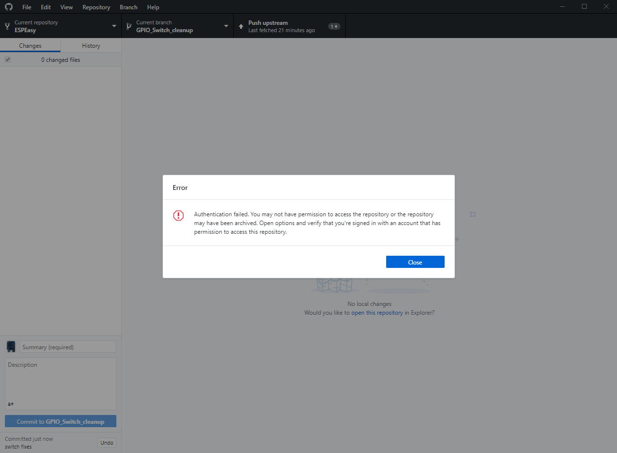
giig1967g
on 12 Dec 2018
What repository are you working on?
Just to make sure you won't loose anything, make a zip file from the directory you're working in.
Git is a great tool, but when starting to mess around in some way not meant to be the 'normal' workflow, you may have trouble finding your commits back :)
I guess you are either working on a repository of me or owned by 'letscontrolit' user.
What you should have done is:
- Work on your own repository
- Add letscontrolit/ESPEasy repository as a remote repository
- Checkout the remote branch
GPIO_Switch_cleanupfrom that remote repository
This creates a new branch on your own (local) repository to which you will add commits.
The origin of your own local repository is your fork of the ESPeasy repository, which is hosted on GitHub.
So if you push your commits, you push the branch you have checked out from your local repository to the origin. This push will very likely then create a branch with the same name GPIO_Switch_cleanup.
Then you continue like you always do and create a PR.
N.B. I assume, since you're working then on the same branch as my PR is based on, is that your pushed commits will very likely be added to my existing PR. (no need to create a PR then)
TD-er
on 12 Dec 2018
I don't remember the steps, but I think that I have selected from github-desktop the repository upstream/gpio_switch_cleanup and then opened in Atom.
I worked on it, compiled and everything was ok.
Commit worked as expected.
But when I pressed PUSH it raised the error.
Will make a backup and start again, hopefully tonight.
Regarding your changes, the changes that you have done on state=-1 is affecting some of the original logic for PCF and MCP because all my controls were assuming 3 possible states (-1,0,1).
But using it as a 2-bit signed int is also asking for trouble.
I am not such an expert, but why this can be a trouble?
giig1967g
on 12 Dec 2018
First it isn't a true 3-state we're dealing with. It is a combination of an error state and a pin state.
You shouldn't merge conceptually different parameters in a single value. That's always something that will bite you in the end.
A get function for those 2 should be something like:
bool getState(bool& pinstate) {
  ...
  return !error;
}
Then you're very much endorsed to check for an error state.
Second is you will not likely get warnings from the compiler when you do something silly which may lead to unexpected behavior.
For example, the state is a signed 2 bit int. ('00' and '01' are positive)
The compiler will accept this, probably without any error or warning:
boolean tmp = state;
if (tmp) { ... }
if (tmp > 0) { ... }
if (state >= 0) { ... }
But what if state was '-1' ?
And putting multiple concepts in the same value, you are still allowed to do this:
if (state != 0) { ... }
if (state) { ... }
Both will do the same, but not what you probably want.
TD-er
on 12 Dec 2018
understood.
But currently in practice, we have the following situations:
1) the read functions for PCF and MCP return 3 possible values. How can this be handled with current data structures? We need to change the read function too. Or encapsulate this function in a another function that split the returned value into two different variables.
int8_t Plugin_019_Read(byte Par1)
{
  int8_t state = -1;
  byte unit = (Par1 - 1) / 8;
  byte port = Par1 - (unit * 8);
  uint8_t address = 0x20 + unit;
  if (unit > 7) address += 0x10;

  // get the current pin status
  Wire.requestFrom(address, (uint8_t)0x1);
  if (Wire.available())
  {
    state = ((Wire.read() & _BV(port - 1)) >> (port - 1));
  }
  return state;
}
2) all the current logic assumes the possibility to have 3 states (as it was before). There is no variable storing an error condition.
What I am saying is that to test the 2-state-only logic, several things must be done in the code and in the pinstate structure.
So either we keep the 3-state-logic or to move to the 2-state-logic you should define the variables and the helper functions and then I will be able to check the full working solution. I am asking you to do it as I might be doing mistakes.
What do you think?
giig1967g
on 12 Dec 2018
What I am saying is that to test the 2-state-only logic, several things must be done in the code and in the pinstate structure.
Either way this has to be repaired.
So I am in favor of changing the read functions of PCF/MCP to something like:
bool Plugin_019_Read(byte Par1, bool& pinstate)
{
  bool success = false;
  const byte unit = (Par1 - 1) / 8;
  const byte port = Par1 - (unit * 8);
  uint8_t address = 0x20 + unit;
  if (unit > 7) address += 0x10;

  // get the current pin status
  Wire.requestFrom(address, (uint8_t)0x1);
  if (Wire.available())
  {
    const byte res = Wire.read();
    pinstate = 0 != ((res & _BV(port - 1)) >> (port - 1));
    success = true;
  }
  return success;
}
N.B. This will also not change the current pinstate value if a value cannot be read.
Edit:
And a pointer to some remark we also should not forget to look at
https://github.com/letscontrolit/ESPEasy/commit/8db694bde6ac91fba994c3ad9fa33e2d461f0e07#commitcomment-31636056
TD-er
on 12 Dec 2018
ok. I will need a week to review everything.
giig1967g
on 12 Dec 2018
@giig1967g What should we do until then about the current change in Switch-logic?
- For the nightly builds revert those changes until we've made it right?
- Add a 'quick fix'?
TD-er
on 12 Dec 2018
I am always afraid of revert and reapply changes.
I am scared that something could go wrong and not be reverted or reapplied properly.
So maybe we could just remove all the releases from github after 20181204.
December 4 release was working ok. Only problem was the title of this topic, in other words to be able to change the pinstate of devices that were declared in the task list.
So the quick fix could be to fix the monitorcommand to be working for GPIO commands and this will allow everyone to rewrite their rules to accomplish what they were doing using the backdoor of the P001 plugin.
I have already written the patch, so I could share it with you and eventually apply it.
In the meantime we rewrite the whole logic.
giig1967g
on 12 Dec 2018
@giig1967g Problem is, if this takes a week (multiple days) and we leave it like it is now, we either have several builds which are in some intermediate state of GPIO functionality, or we have to wait building a new one until this is solved.
There are more issues reported regarding the GPIO-changes. (and move of commands away from P001)
TD-er
on 12 Dec 2018
@TD-er what is the slack channel for this project?
giig1967g
on 12 Dec 2018
@giig1967g
espeasy.slack.com
TD-er
on 12 Dec 2018
do I need an invitation?
giig1967g
on 12 Dec 2018
Yes, you can PM me a email address (use the forum).
 Grovkillen
on 12 Dec 2018
Grovkillen
on 12 Dec 2018
@Grovkillen
I sent a PM
giig1967g
on 12 Dec 2018
@giig1967g I named you Plebs.. you can decide your own name once on Slack :)
Grovkillen
on 12 Dec 2018
@giig1967g What should we do until then about the current change in Switch-logic?
* For the nightly builds revert those changes until we've made it right?

* Add a 'quick fix'?
@TD-er
I have made up my mind. I would revert the changes to 20181204.
giig1967g
on 12 Dec 2018
Will do tomorrow :)
TD-er
on 12 Dec 2018
@giig1967g
I am trying to revert the switch code of 20181204. See https://github.com/letscontrolit/ESPEasy/pull/2161 (including test build)
But in my test setup, a P001 switch (output) is not responding in the devices overview page.
Any idea what I'm missing here?
Rules:
on Button1#switch do
  if [Button1#switch]=1
    gpio,12,1
  else
    gpio,12,0
  endif
endon
The LED of the relais is reacting and the "Value/State" on the pin state page is showing the correct value.
Unconditional Poll is not updating the state, since task == 1.
TD-er
on 13 Dec 2018
reverting to 20181204 doesn't fix the gpio output switch as it's blocked as per our discussion in here:
https://github.com/letscontrolit/ESPEasy/issues/2112#issuecomment-443374544
We have two options:
1) Allow the P001 switch output: I have just to change a couple of lines of code.
2) Don't allow P001 switch output (as it should be!) and solve it using the monitor command. In the monitor command (as already informed) there is currently a bug that I need to fix, as soon as I have access to the final version:
So the code will become:
on System#boot do
monitor,gpio,13
endon

on GPIO#13 do
  if [PLUGIN#GPIO#PINSTATE#13]=1
    gpio,12,1
  else
    gpio,12,0
  endif
endon
My understanding was that we will be using the 2nd option.
giig1967g
on 14 Dec 2018
For now, I changes 2 lines of code to allow the old behavior for now.
This will give us time/room to make it right.
I agree on what it should eventually be, which is that the p001 switch module should have an extra option to explicit set it to an output mode. (or the same base logic and a separate plugin, but that's an implementation choice, not a global design choice)
In essence the plugin should be clear on what to do and explicitly set to do so.
Maybe the monitoring state can also be set at bootstate, where we also define the pull-up resistors.
TD-er
on 14 Dec 2018
Ok. For some obscure reasons I cannot access my PCfrom office today...
Your change looks fine, but will have to check in my PC to compare the versions and my notes.
In case, same change should be done to PCF and MCP.
Will review tonight at home
giig1967g
on 14 Dec 2018
Is there an actual difference between :
monitor,gpio,
and
status,gpio,
status returns if the gpio is not defined (either high or low) initially (except for gpio,0 !!!)
while monitor returns "mode": "undefined", "state": 65535 also when the gpio is not defined.
When the gpio is defined they both return the same string.
-D
 ironataerial
on 26 Dec 2018
ironataerial
on 26 Dec 2018
there is a PR in assessment that will correct some of the issues you are reporting.
But the difference between status and monitor is that status returns only a JSON message, while monitor will create an event in the rules.
giig1967g
on 26 Dec 2018
Any news here? Is the PR mentioned above already assessed?
kristi5
on 2 Jul 2019
@kristi5
many changes have been done since this ticket.
Could you please summaruze with an example what is the current problem?
giig1967g
on 2 Jul 2019
Hi, please let me continue this thread as it is open.
I am confused as this is treated in many places here, on the forum and elsewhere and I cant figure out the actual state of this issue.
I recently created a task (P001) for every output relay on my house, based on a suggestion I found on the forum. Just as I finished I found that my poorest wifi device was not changing the task status on local output pin change (stupid me I know).
My example problem:
I have a device that keeps loosing wifi and MQTT connection;
I dont want to retain its status at the controller (for obvious reasons);
It has a push button on a pin that changes an output pin (relay);
Sometimes a publish on change wont work for the reason above;
I need it to periodically send its status to the controller so to keep sync.
Can you please show me the way to accomplish that?
Git Build: | mega-20200703
Rules for pushbutton (these publish may get lost too, but this is not that serious):
on Suite1#State=1 do
 timerSet,1,1
EndOn

on Suite1#State=0 do
 timerSet,1,1
EndOn

On Rules#Timer=1 do
 gpiotoggle,5
 Publish ESP-Suite2/Suite1,single
 timerSet,1,0
endon

on Suite1#State=3 do
 Publish ESP-Suite2/Suite1,double
 timerSet,1,0
EndOn
 fnees
on 7 Sep 2020
fnees
on 7 Sep 2020
Well first of all, I think it is better to match a single block on the event name Suite1#State and then process the %eventvalue% (0, 1, 3 in your rules)
I also strongly suggest to use logentry for debugging, as I doubt the eventvalues here will be 3 here. (See LogEntry command reference )
And for "how to use questions" it is best to use the forum.
Github issues are for "This not working, you go fix, yes?" kinda questions.
And I know the P001 switch plugin isn't working as nicely as it should be and in desparate need of some TLC, I don't think it is broken right now.
TD-er
on 7 Sep 2020
Yeah, sure you are right! Sorry about that question.
The reason I posted here was for your last comment on this issue:
"For now, I changes 2 lines of code to allow the old behavior for now.
This will give us time/room to make it right".
And as it is open I presumed that behavior was to be allowed and the issue in the roadmap for getting addressed, whether it being officially allowed, or by a new output switch plugin, or... then I got the "many changes have been done since this ticket" from @giig1967g.
So the right questions were:
Is this addressed? Should I still be able to use it for monitoring an output switch with a task? If so, is my build bugged?
PS.:Thank You so much for your response and insights!! The rules work perfectly, I just posted here as they are on the device mentioned and to illustrate a Publish solution that doesnt work for my needs. The reason they are written that way is because eventvalue always changes to 0 or 1 before changing to 3. So I put them on hold until the eventvalue 3 appears (or not, then I publish single for 0 or 1 whatever it toggled to). This is also strange as the device gets stuck on 0 or 1 even if last change was to 3 (and probably so if it ever gets to 10, which I couldnt get as I cant see how to get the longpress working... but that is me being a noob)
fnees
on 7 Sep 2020
Well the current state is sadly that the GPIO handling is still not entirely how it should be.
@giig1967g was also asking me yesterday in the Slack about it.
By accident, I also found an issue which may affect PLUGIN_TIMER_IN calls, which is also used by the switch plugin.
So when in doubt about the port state, you may also want to test a build of roughly 2 months ago. (will be fixed in the next build too)
TD-er
on 7 Sep 2020
Related issues
Grovkillen
·
6Comments
 jobst
·
5Comments
jobst
·
5Comments
 DittelHome
·
5Comments
DittelHome
·
5Comments
 ronnythomas
·
3Comments
ronnythomas
·
3Comments
 hamed-ta
·
5Comments
hamed-ta
·
5Comments
Most helpful comment
@thomastech
What are you actually missing right now?
The current implementation of switch is (and was) flawed, or incomplete to say the least.
The main issue is (and was) we simply had too much options to alter and read the state of a GPIO pin, which can lead to very serious bugs, since updates or state changes were missed.
Also setting a GPIO and having a switch plugin connected to that pin with the "inverse logic" flag enabled would lead to strange results.
So the main reasons we want things to change this:
And thus we came up with the idea to make them just very simple:
An input switch should only accept remote state changes, when not directly coupled to a GPIO state.
But as I read your issues, it seems like this is a bit "too basic".
So can you give a list of things you need a switch plugin (or GPIO plugin) to do?
For example:
Any more needs?
This is where we want to go to, but we're not there yet.