Espeasy: DHT12: No reading! - on Sonoff touch extended with standard DHT12 running version 148 AND mega-20181101_normal_ESP8285_1024
Summarize of the problem/feature request
A custom attached dht12 on a sonoff touch is initally recognized by i2c scan but does not have any reading after added and even disappears from i2c busscan after it is added as a device.
Expected behavior
critical:
- The DHT12 should have a temp/hum reading & show them on the device page
nice to have: (if this is only display errors and not functional)
- The device should display nan / NAN uniformly.
- the DHT12 should continue to appear in the I2C scan
Actual behavior
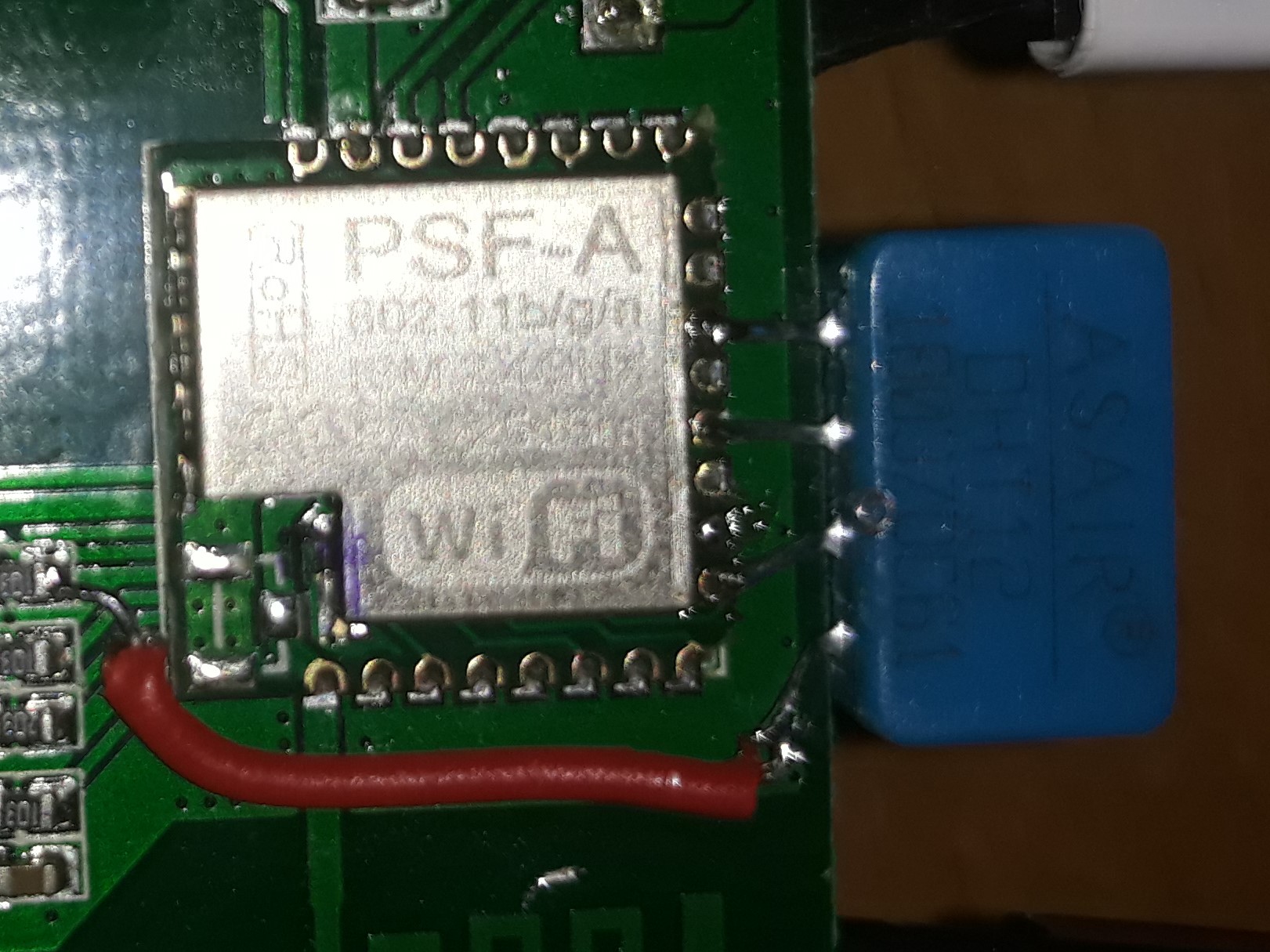
I have attached a standard DHT12 sensor on the following pins to a sonoff touch EU V1.0
GPIO10<->SCL
GND <->GND
GPIO2<-> SDA
ESP8285 3V3<->DHT Vcc
- The standard device & functions (light, switch, wifi) are ok & it is stable
- The I2C bus shows the DHT12 at 0x5C
- The DHT 12 can be added and shows in the logs:
1382762: LoopStats: shortestLoop: 88 longestLoop: 1629107 avgLoopDuration: 104.33 loopCounterMax: 340909 loopCounterLast: 280623 countFi
1382763: PluginStats P_33_Environment - DHT12 (I2C) ONCE_A_SECOND Count: 30 Avg/min/max 15.70/11/20 usec
1382764: PluginStats P_33_Environment - DHT12 (I2C) TEN_PER_SECOND Count: 300 Avg/min/max 7.07/7/12 usec
1382764: PluginStats P_33_Environment - DHT12 (I2C) FIFTY_PER_SECOND Count: 1499 Avg/min/max 9.56/2/42 usec
1382765: Plugin call 50 p/s stats: Count: 1499 Avg/min/max 666.13/530/1014 usec
1382765: Plugin call 10 p/s stats: Count: 300 Avg/min/max 587.75/552/874 usec
1382766: Plugin call 10 p/s U stats: Count: 300 Avg/min/max 750.26/565/1086 usec
1382766: Plugin call 1 p/s stats: Count: 30 Avg/min/max 1227.67/1114/1306 usec
1382766: setNewTimerAt() stats: Count: 2131 Avg/min/max 149.40/116/229 usec
1382767: timeDiff() stats: Count: 901064 - CPU cycles per call: 9.40
1382767: Scheduler stats: (called/tasks/max_length/idle%) 280623/2131/7/92.10
1412337: DHT12: No reading!
However there is also a strange / odd behavior:
- "No reading" in the logs (see above)
- Values in device tab read "nan" (in small) shortly after that being "auto refreshed" (?) by "NaN" (in Caps; looks odd but it might just be a display issue.
- Once the Device is added under Devices, it does no longer appear in the I2C Busscan ("No I2C devices found")
- when removing the device it reappears in the I2C Busscan after a reboot (this is a different behavior than with other DHT12 and I2C devices I use here - for example one on ESP_Easy_mega-20180815_normal_ESP8266_4096.bin and also older/stable 1xx releases of the ESP8285. The Devices are always shown in the scan when they are attached - any reason why shouldnt it?
- the latter two behaviours can be repeated back and forth by adding / removing the device.
have searched the KB and only found some very loosely related issues - for example #1798 which is not comparable because: Version, hardware and symptom are all different.
Steps to reproduce
- attach dht12 on the sonoff touch
- configure i2c to GPIO10<->SCL; GPIO2<-> SDA
- save & restart
- i2c scan - dht12 is found at 0x5C
- add dht12 as a device
- save & restart
- no dht12 readings in log
- no tempo /hum shown in log / device ("No Reading")
- Device not present in i2c scan
- remove i2c device from list
- save & restart
- i2c scan works again , device dht12 is found at 0x5C
The device was restetted, reflashed and switched of multipe times.
restarting the unit after removing the device makes i2c work again as described in repro steps.
System configuration
Hardware: I have attached a standard DHT12 sensor on the following pins to a sonoff touch EU V1.0
Build:20102 - Mega
Libraries: ESP82xx Core 00000000, NONOS SDK 2.2.1(cfd48f3), LWIP: 2.0.3
GIT version:mega-20181101
Plugins:46 [Normal]
Build time:Nov 1 2018 03:22:25
Binary filename:ESP_Easy_mega-20181101_normal_ESP8285_1024.bin
- Multiple tries erasing / reflashing did not change a Thing / had the same behaviour.
- adding it NOT as the leading task but as 2 or 5 ( see: interrupt specifics for counting devices) has the same effect.
One thing I can still do is
- set it up on a totally different sonoff touch ad use a different dht12. That IU have not done yet. let me know if I should do this or if you are able the reproduce the error like this .
- self compile (if that helps ...?)
ESP Easy version:
ESP Easy settings/screenshots:
(1) Tools before adding:
I2C Addresses in use | Supported devices
0x5C | DHT12AM2320BH1750MPR121
adding & enabling a device:
(2) Display
Task | Enabled | Device | Name | Port | Ctr (IDX) | GPIO | Values
-- | -- | -- | -- | -- | -- | -- | --
Edit | 1 | ✔ | Environment - DHT12 (I2C) | t | | | GPIO-2GPIO-10 | Temperature:NaNHumidity:NaN
(3) Tools after adding:
No I2C devices found
I2C Addresses in use | Supported devices
Rules or log data
- rules have been disabled and have no effect.
- Serial Port was disabled in all tests as gpio2 was used for I2c sda
- Serial Noise from PC can be excluded as the problem persits while powerd by AC / Standard Sonoff with Serial cable fully disconnected.
- EXACT same Problem with completly different hardware from same batch (switch & dht12) and espeasy Build 148/2_3_0. is there something fishy with the pins I use? I checked https://hackaday.io/project/28220-one-tube-nixie-clock/log/70865-esp8285-gpio
=> GPIO2 as SDA seems to be the problem!
"Boot mode select/TX1 | Can't be used as an input. There is an external pull-up on this pin, so it also can't be used for applications that require Hi-Z (such as I2C). | HV Enable"
If that is the case it should not be possible to select it in the list .. please ;)
- will investigate but any hint warmily welcome!
 pawart
All 11 comments
I think adding at least an exclamation mark (like added on some pins at the last few builds is done) is a good idea.
And we should add a proper documentation link to the pin descriptions.
Indeed GPIO-2 may be causing some issues.
Usually GPIO 4 & 5 are used for I2C
 TD-er
on 18 Nov 2018
TD-er
on 18 Nov 2018
Jup.
Also included should be this one - see below ...
It shows the BUILT in Resistors (UP And down!!!) that are already there in an esp8266 and might interfere otherwise. I was not aware of this for quite some time and it explained some symptoms I had years ago!
-x-
Pin Function ESP-8266 Pin
TX TXD TXD
RX RXD RXD
A0 Analog input, max 3.3V input A0
D0 IO GPIO16
D1 IO, SCL GPIO5
D2 IO, SDA GPIO4
D3 IO, 10k Pull-up GPIO0
D4 IO, 10k Pull-up, BUILTIN_LED GPIO2
D5 IO, SCK GPIO14
D6 IO, MISO GPIO12
D7 IO, MOSI GPIO13
D8 IO, 10k Pull-down, SS GPIO15
G Ground GND
5V 5V -
3V3 3.3V 3.3V
RST Reset RST
pawart
on 18 Nov 2018
:+1:
maybe add a note that the pull ups and down are needed for normal booting. If you tie them anywhere else, the ESP will not boot (from flash).
 s0170071
on 18 Nov 2018
s0170071
on 18 Nov 2018
Just as a screenshot of what is currently being shown in the GPIO selection combobox (for ESP8266)
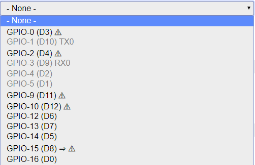
It is of one of my nodes, so already used pins are greyed out.
It just needs a proper documentation link next to such a combo box.
TD-er
on 19 Nov 2018
But grey pins can still be selected, right?
s0170071
on 21 Nov 2018
@s0170071 It appears that greyed out pins cannot be selected. They will not highlight and clicking on them has no effect.
Mega 20181121
Edit....
If a pin is already used as a input switch it will not be greyed out and can be selected.
The only greyed out pins are 1, 3, 4 and 5. These are serial and I2c.. (in my setup which is default.)
So it seems to be possible to select an "in use" pin. FWIW
 Budman1758
on 21 Nov 2018
Budman1758
on 21 Nov 2018
That's unfortunate. I use the sht25 plugin and have multiple sensors sharing the data line. I select the pins in the plugin. I need to be able to select pins in every combination.
I2c is purely software btw. There are no dedicated pins afaik.
s0170071
on 21 Nov 2018
Just for the hell of it I tested another scenario. Flashed a unit and disabled both serial and I2c and those pins then became available as inputs. (not greyed out). I set one as a switch input device. (pin 4)
Then went to another switch input device and pin 4 was not greyed out and could be selected again.
So they are only greyed out and unavailable if they are set as either serial or I2c. Also seems no matter which pins you chose for serial or I2C those will be unavailable.
Is this the expected behaviour?
Budman1758
on 21 Nov 2018
This is by design yes. I need to get up to speed on the documentation... ;)
 Grovkillen
on 21 Nov 2018
Grovkillen
on 21 Nov 2018
It is indeed by design.
Greyed out pins are already dedicated for other purposes like serial and I2C.
When a pin is set to be used for a plugin, it will not be disabled to be used for other plugins.
So you can have multiple plugins share the same pin, which is also needed for some plugins like the Dallas 1wire sensors and a switch plugin. (input OR output, not AND)
TD-er
on 21 Nov 2018
any update here?
 uzi18
on 4 Sep 2019
uzi18
on 4 Sep 2019
Related issues
 Wandmalfarbe
·
5Comments
Wandmalfarbe
·
5Comments
 SANCLA
·
4Comments
SANCLA
·
4Comments
 jroux1
·
6Comments
jroux1
·
6Comments
 ronnythomas
·
3Comments
TD-er
·
5Comments
ronnythomas
·
3Comments
TD-er
·
5Comments