Espeasy: PCF8574 Inputs stop responding when other pins used as output.
Steps to reproduce
How can we trigger this problem?
Set up a PCF8574 with 4 outputs and 4 inputs. Set up 4 as input switches as 4 tasks. Or 3 as in my setup.
Does the problem presist after powering off and on? (just resetting isnt enough sometimes)
Yes
Expected behavior
When powered up at first inputs respond as they should. I have 2 reed switches to simulate a door open and closed position indicator. When each switch is actuated I have a rule that writes a line on an OLED display. Works great until ANY of the outputs are triggered.
Actual behavior
When 1 output is triggered 1 of the 2 inputs stops responding. When you trigger another output the second input stops responding. Only way to get the inputs to respond again is to power cycle the setup.
System configuration
-01 module. PCF8574 IO expander. OLED display module (I2C) SI7102 temp and humidity sensor. 4 channel relay board. Temp sensor and OLED module all work fine.
Ports 1-4 set as inputs and ports 5-8 connected to relays.
3 tasks for 3 switch inputs to PCF8574.
This is consistent and repeatable with 3 or 4 different PCF8574 chips I have and have tried several different "late model" ESP releases. Right now using >> GIT version: | mega-20180111
I thought I was imaging this but its VERY consistent. After messing around with this for the last 2 days I'm afraid I have no more hair to pull out. Wasn't much to start with tho.....
Let me know what you need as to screenshots or configs.
BTW. The logic is reversed on this chip. It takes a "0" to get a positive output. That normal?? Seems kinda backwards. That had me going for a while......
 Budman1758
All 83 comments
I must confirm, Pcf8574 expander plugin is unreliable sometimes.
Did some test in the past on 2.0 firmware, with mixed inputs/outputs but it
was sometimes unpredictable.
Did not found solution.
In keypad plugin it is working ok.
Maybe because it is splitted into pins in device configuration.
12.01.2018 8:35 AM "Carl Forster" notifications@github.com napisał(a):
Steps to reproduce
How can we trigger this problem?
Set up a PCF8574 with 4 outputs and 4 inputs. Set up 4 as input switches
as 4 tasks. Or 3 as in my setup.Does the problem presist after powering off and on? (just resetting isnt
enough sometimes)
Yes
Expected behaviorWhen powered up at first inputs respond as they should. I have 2 reed
switches to simulate a door open and closed position indicator. When each
switch is actuated I have a rule that writes a line on an OLED display.
Works great until ANY of the outputs are triggered.
Actual behaviorWhen 1 output is triggered 1 of the 2 inputs stops responding. When you
trigger another output the second input stops responding. Only way to get
the inputs to respond again is to power cycle the setup.
System configuration-01 module. PCF8574 IO expander. OLED display module (I2C) SI7102 temp and
humidity sensor. 4 channel relay board. Temp sensor and OLED module all
work fine.
Ports 1-4 set as inputs and ports 5-8 connected to relays.
3 tasks for 3 switch inputs to PCF8574.This is consistent and repeatable with 3 or 4 different PCF8574 chips I
have and have tried several different "late model" ESP releases. Right now
using >> GIT version: | mega-20180111I thought I was imaging this but its VERY consistent. After messing around
with this for the last 2 days I'm afraid I have no more hair to pull out.
Wasn't much to start with tho.....Let me know what you need as to screenshots or configs.
BTW. The logic is reversed on this chip. It takes a "0" to get a positive
output. That normal?? Seems kinda backwards. That had me going for a
while......—
You are receiving this because you are subscribed to this thread.
Reply to this email directly, view it on GitHub
https://github.com/letscontrolit/ESPEasy/issues/702, or mute the thread
https://github.com/notifications/unsubscribe-auth/AAHOU5kDfSaMxTGrUPsiyhcjUxLoMc7kks5tJwsvgaJpZM4Rb6UD
.
 uzi18
on 12 Jan 2018
uzi18
on 12 Jan 2018
I already described this problem on issue #222 (sorry for my poor english):
PCF8574 documentation states "The I/Os should be HIGH before being used as inputs." (https://www.nxp.com/documents/data_sheet/PCF8574.pdf section 7.3).
In function Plugin_019_Write to write an output pin first it reads all pins, then set the pin and write all pins.
If coincide an input pin reads LOW, then writes that pin as LOW and that pin leaves to be input pin. That pin always reads LOW until PCF8574 restart (or until explici writes HIGH to that pin; now I make that on rules after write an output pin).
I think the solution is to keep a mask in the module and set to HIGH all pins defined as inputs. Then in function Plugin_019_Write apply the mask when read all pins, so all input pins are set to HIGH.
 svmac
on 12 Jan 2018
svmac
on 12 Jan 2018
I even tried with external pullups and they had no effect.
Budman1758
on 12 Jan 2018
Yes, because chip tied it into gnd internally
2018-01-12 19:07 GMT+01:00 Carl Forster notifications@github.com:
I even tried with external pullups and they had no effect.
—
You are receiving this because you commented.
Reply to this email directly, view it on GitHub
https://github.com/letscontrolit/ESPEasy/issues/702#issuecomment-357307614,
or mute the thread
https://github.com/notifications/unsubscribe-auth/AAHOU0Zo7MggYpEcJB9KQmMvPWTBrVorks5tJ5yfgaJpZM4Rb6UD
.
uzi18
on 12 Jan 2018
Thanks for confirming the problem. I thought I was going crazy for a while there.... :)
Also, whats with the inverted logic? When the pin is "High" (positive voltage) on the device page for the task it shows "0". That makes things confusing for making logic rules.
Budman1758
on 12 Jan 2018
If it is really as confusing as you describe, maybe we should hide the abstraction level from the plugin user and make it "easy" again.
If I remember correctly, the chip just arrived in the mail last week.
 TD-er
on 12 Jan 2018
TD-er
on 12 Jan 2018
Once you realise the logic is backwards it's not that big a deal. My question is why is it backwards in the first place? Kinda goes against the whole "high" vs "low" logic scheme used everywhere else.
Budman1758
on 12 Jan 2018
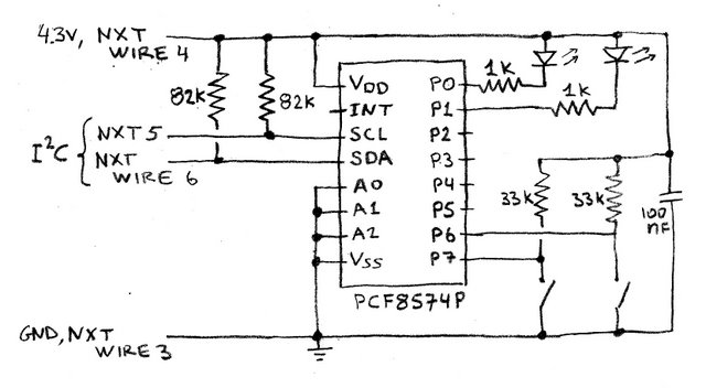
I remember the chip logic was a bit counter-intuitive.
You have to write a "0" to it to bind the pin to ground.
This means if you connect a LED via a resistor to the Vcc, the LED will go on when writing a 0 to the pin.
So write a 0 to force as an output.
Write a 1 to allow it to be an input.
So connect a pin via a pull-up resistor to the Vcc.
If you write a 1 to it, the pin will be pulled high by the resistor and you can pull it down to ground via a switch. Then it is an input you can read. (switch "open" is signal is high)
When you write a 0 to it, the level will be pulled to gnd, so the signal is low.
This also means you cannot use it as an input since the pin is connected to GND.
A very descriptive picture about this "strange" IC:
TD-er
on 12 Jan 2018
On my setup you had to type "0" in your command to make the output high. (positive voltage output).
pcfgpio,0 >> relay on
pcfgpio,1 >> relay off
The relay is +voltage to turn on.
Budman1758
on 12 Jan 2018
But how is your relay connected? I imagine exactly like the LED in the drawing I posted?
So write a 0 and the pin will be connected to ground and thus a current will flow from Vcc through the relais, through the IC to the GND.
Write a 1 and the pin of the chip will be floating and thus no current will flow.
TD-er
on 12 Jan 2018
Sorry. I had part of that backwards. PCF8574 outputs are high and relay is off. Write "0" and relay goes on.
I had thought my relay board were "high" trigger. Turns out they are "low" trigger. So I guess the logic is right. Still have the original issue tho.......
Budman1758
on 12 Jan 2018
I think this is not a strange IC, but it have open collector outputs (see https://en.m.wikipedia.org/wiki/Open_collector) that is a common and simple way to make input/output pins.
The problem is in the plugin, on how it makes the output. I see 3 solutions:
1) don’t mix input and output on the same IC. Use all inputs or all outputs IC.
2) every time writes an output pin, must write 1 on every pin assigned as input
3) correct the plugin
svmac
on 14 Jan 2018
Just provide one more command to set where is input and remember it in
plugin.
14.01.2018 1:04 PM "svmac" notifications@github.com napisał(a):
I think this is not a strange IC, but it have open collector outputs (see
https://en.m.wikipedia.org/wiki/Open_collector) that is a common and
simple way to make input/output pins.
The problem is in the plugin, on how it makes the output. I see 3
solutions:
- don’t mix input and output on the same IC. Use all inputs or all
outputs IC.- every time writes an output pin, must write 1 on every pin assigned
as input- correct the plugin
—
You are receiving this because you commented.
Reply to this email directly, view it on GitHub
https://github.com/letscontrolit/ESPEasy/issues/702#issuecomment-357507081,
or mute the thread
https://github.com/notifications/unsubscribe-auth/AAHOU6DAAj-Rsho3c3YpqMbROWscgvpyks5tKe1HgaJpZM4Rb6UD
.
uzi18
on 14 Jan 2018
i've ordered this chip myself, cant test anything now :)
 psy0rz
on 15 Jan 2018
psy0rz
on 15 Jan 2018
Should have told me ya needed one. I would send you a couple for free if you can fix the plugin. I've got 20 of them. :)
Budman1758
on 15 Jan 2018
i live in the netherlands, and they are only $1.30 for 5 pcs. with free shipping on aliexpress ;)
psy0rz
on 15 Jan 2018
I'm working on fix for this and #222, almost there.
@psy0rz @TD-er, what is idea behind set/getPinState, do we need also store there input state?
uzi18
on 18 Feb 2018
should be fixed, please reopen if this problem still exists.
psy0rz
on 26 Feb 2018
the problem still exists. I try with 4 output (relay active gnd) and 4 input (door switch to gnd), input work well but output works only 2 time after that is it randomly.
 beaulif
on 5 Aug 2018
beaulif
on 5 Aug 2018
what versions did you test? What is your last version when it work as
expected?
show your configuration and test case please
niedz., 5.08.2018, 03:02 użytkownik Gijs Noorlander <
[email protected]> napisał:
Reopened #702 https://github.com/letscontrolit/ESPEasy/issues/702.
—
You are receiving this because you commented.
Reply to this email directly, view it on GitHub
https://github.com/letscontrolit/ESPEasy/issues/702#event-1771436495,
or mute the thread
https://github.com/notifications/unsubscribe-auth/AAHOU5RUo4z-1To6sUoyRn7-R_bELNIuks5uNkQkgaJpZM4Rb6UD
.
uzi18
on 5 Aug 2018
i try this version ESP_Easy_mega-20180802_normal_ESP8266_4096.bin.
for input i use 4 door switch to gnd

for output i use relay arduino actif low with optocoupler Vcc=3.3volt JDVcc=5volt see shematic of relay:

beaulif
on 5 Aug 2018
and esp configuration?
uzi18
on 5 Aug 2018
esp config?
for output relay i use this command:
active relay 1= http://192.168.0.30/control?cmd=PCFPulse,17,0,4250
active relay 2= http://192.168.0.30/control?cmd=PCFPulse,18,0,4250
active relay 3= http://192.168.0.30/control?cmd=PCFPulse,19,0,4250
active relay 4= http://192.168.0.30/control?cmd=PCFPulse,20,0,4250


beaulif
on 5 Aug 2018
We fixed pcfgpio command, but did not check pcfpulse command ok now we know where to search, for me it is not related to this issue.
@TD-er is it not related to new timers?
uzi18
on 5 Aug 2018
the input works well but, not the output. After activating relay 1 for 4.5 sec the other relays remain active.No matter which relay I activate the others remains activated after the delay.
this afternoon I did another test with a MCP23017 and everything works well I can use my relays and my door contact without problem.
I think that it would be necessary to modify the plugin of the PCF8574 to freeze the input output at initialization.
sorry for my poor english
beaulif
on 5 Aug 2018
thx for info, will try to find solution
uzi18
on 5 Aug 2018
What if you execute once:
PCFgpio,17,1
PCFgpio,18,1
PCFgpio,19,1
PCFgpio,20,1
and next execute pcfpulse commands, is it ok than?
uzi18
on 5 Aug 2018
@uzi18 It is very unlikely the new timers cause these issues.
I would expect something in parsing of commands.
TD-er
on 6 Aug 2018
I see here different problem, but we will wait for tests with pcfgpio commands before pcfpulse.
@TD-er only pcflongpulse use system timers.
pcfpulse use delay() function here.
uzi18
on 6 Aug 2018
Well then those should be using the timers too.
Let's make sure they fail the same ;)
TD-er
on 6 Aug 2018
@uzi18 I wass thinking about your remark.
Can you take a look when the jobs are being scheduled and what their IDs are in the scheduler?
If the on/off jobs are scheduled at the same time (or at least the second one before the first has been processed) and share the same ID, then the first one will be removed from the scheduler.
TD-er
on 6 Aug 2018
@beaulif we need your feedback here
@TD-er i'm thinking about something more simple - if pcfgpio is not marked as output state is unpredictable and for now we wait for feedback or will test it at the evening...
uzi18
on 6 Aug 2018
ok i did the tests asked.
PCFgpio ok
pcfpulse and pcflongpulse do not work, after sending a pulse to 1 relay all other relays remain activated.
beaulif
on 6 Aug 2018
@TD-er @beaulif
sorry can't reproduce this, everything works fine
uzi18
on 8 Aug 2018
@TD-er small PR #1635 is ready to marge :D
uzi18
on 8 Aug 2018
@uzi18 I just resolved the merge conflict.
TD-er
on 8 Aug 2018
thx, my git repo is some commits behind ;)
uzi18
on 8 Aug 2018
@TD-er still learning how to work with ... platformio - any hint how to upload specific target? upload always choose esp32dev target ...
uzi18
on 8 Aug 2018
When using Atom as editor, you can click in the lower left bottom.
This will open a window with all the settings.
I usually start typing there like "upload normal" to get a smaller selection to choose from.
Just make sure to select the right one :)
And I found the detection of the uart settings to work best when I press and hold flash and short press reset and then release the flash after a few seconds. (NodeMCU board)
PlatformIO sometimes does not detect the UART settings right the first time.
TD-er
on 8 Aug 2018
@beaulif please test tommorows build/release if will be available
uzi18
on 8 Aug 2018
there seems to be another issue with the PCF GPIO. if you connect active-high SSR's to the PCF the change of state is never actively sent back.
I defined a task as switch-input pin1 wich shows default 1, when then setting this pin via pcfgpio,1,0 the task stays on 1 and no event is created.. also if I switch back then to 1 no event is created.
as I understand the ten_per_second function it should create a event whenever the level of the respective pin changed.
if I do a "status,pcf,1" it shows me the correct value though (so only the switch input task is not updated...)
interestingly I don't have this issue with low-level triggered normal relay's....
Of course it's easy to work around with a inputswitchstate and taskrun statement... but that's not a really clean solution...
 clumsy-stefan
on 9 Aug 2018
clumsy-stefan
on 9 Aug 2018
@beaulif please test tommorows build/release if will be available
ok it is work now for pcfpulse and pcflongpulse
thank's
beaulif
on 9 Aug 2018
@clumsy-stefan please show me how You connect this ssr (drawing)
maybe it is pcf hardware design problem?
@TD-er do we need to generate event for gpio - output pin?
Switch/mcp/pcf does not generate such events.
uzi18
on 9 Aug 2018
the SSR inputs are connected directly to the PCF's I/O, GND-GND, VCC - 5V
Wemos D1 Mini same GND and 5V
PCF same GND and 5V plus SCL/SDA for I2C
clumsy-stefan
on 9 Aug 2018
any link for such inputs??
uzi18
on 9 Aug 2018
SSR: https://www.sainsmart.com/products/4-channel-5v-solid-state-relay-module
PCF8547: https://www.aliexpress.com/item/10PCS-LOT-PCF8574-IO-Expansion-Board-I-O-Expander-I2C-Bus-Evaluation-Development-Module/32441083879.html?spm=2114.search0104.3.15.37d46dbaBXXdxW&ws_ab_test=searchweb0_0,searchweb201602_5_10152_10151_10065_10344_10068_10342_10343_10340_10341_10696_10084_10083_5011815_10618_10307_5723615_10134_5011715_10059_100031_10103_10624_10623_10622_10621_10620,searchweb201603_1,ppcSwitch_5&algo_expid=6f45c29f-18fb-4269-b38b-732cc0906a05-2&algo_pvid=6f45c29f-18fb-4269-b38b-732cc0906a05&priceBeautifyAB=0
Wemos D1 Mini: https://wiki.wemos.cc/products:d1:d1_mini
clumsy-stefan
on 9 Aug 2018
why we need to generate such event?
uzi18
on 10 Aug 2018
@uzi18
do we need to generate event for gpio - output pin?
Switch/mcp/pcf does not generate such events.
I have not really looked at the code of this plugin.
Which event do you mean?
sendData for example is normally used to update controllers to send a state (often from 10/sec or 50/sec calls) and SensorSendTask, which does eventually call sendData , is being called on those plugins dat need to do a PLUGIN_READ and apply formula's and stuff.
These are all functions that send out an event.
Is there some other case here what is sending events?
TD-er
on 10 Aug 2018
look at the post of stefan, he want to generate event about gpio goes 1 or 0 when he execute pcfgpio command, for. me it is something new to consideration, thats why I am asking you what do You think about it.
for me it is dangerous as it will relaunch rules every time gpio will change.
uzi18
on 10 Aug 2018
I have also very recently learned about these events and how they are sent and being dealt with.
For example my notes of yesterday when looking into the MessageDelay:
DeviceTimer:  (per Plugin, run each <interval> seconds)

Initial schedule at boot and when connected to WiFi/MQTT:

    void schedule_task_device_timer_at_init(task_index)
        schedule_task_device_timer(task_index, runAt);


Called from the Scheduler:

    void process_task_device_timer
        if (TaskDeviceTimer[task_index] != 0)
            schedule_task_device_timer(task_index, newtimer);
        SensorSendTask(task_index);


    void SensorSendTask(byte TaskIndex)
        if (PluginCall(PLUGIN_READ...
            Process TaskDeviceFormula
            sendData


    void sendData(event)
      per controller:
        CPlugin_ptr[event->ProtocolIndex](CPLUGIN_PROTOCOL_SEND, event, dummyString);

      PluginCall(PLUGIN_EVENT_OUT, event, dummyString);    => Not being used!!!!


Called by a lot of plugins from:
  10/sec
  50/sec
    sendData(event)
This sendData does pause the entire system for the set MessageDelay.
So I totally agree sending lots of events can be very tricky.
On the other hand, I don't know if they are needed at some controller.
I really would like to make the proper GPIO handler to deal with these changes at 1 place, for all GPIO's.
I don't think the controllers need to be updated on every GPIO change, except when some controller is subscribing to it, but then use something like a dummy device.
A proper fix to me would be to use these extra GPIO's just the same as normal GPIOs and then a plugin like Switch can decide if it is needed to send an event.
The general/central (pick your name) GPIO handler can just schedule such a plugin to have a look at the pins, because one has changed and then decide to send an event.
Sending an event on all changes looks to me like a bad fix for this problem.
TD-er
on 10 Aug 2018
when you look at P019 (PCF8574) it does the following:
case PLUGIN_TEN_PER_SECOND:
  {
    int state = Plugin_019_Read(Settings.TaskDevicePort[event->TaskIndex]);
    if (state != -1)
    {
      if (state != switchstate[event->TaskIndex])
      {
        String log = F("PCF  : State ");
        log += state;
        addLog(LOG_LEVEL_INFO, log);
        switchstate[event->TaskIndex] = state;
        UserVar[event->BaseVarIndex] = state;
        event->sensorType = SENSOR_TYPE_SWITCH;
        sendData(event);
      }
    }
    success = true;
    break;
  }
As I understand this part, it means, that whenever a PIN that is defined as an input in a task is changing it's value, it should generate an event and update the respective value.
This seems to work partially. Especially when using low-level-triggered relays. but it seems to fail with hig-level-triggered SSR's.
What I think is strange is, that when you do a explicit "status,pcf,
I'm still trying to debug what exactly happens, but couldn't get to the cause yet... so any ideas / pointers are welcome!
clumsy-stefan
on 10 Aug 2018
Hmm looking at that code makes my code senses tingle.
Look at this beauty in the Plugin_019_Write function:
if(!getPinState(PLUGIN_ID_019, unit, &mode, &value) || mode == PIN_MODE_INPUT || (mode == PIN_MODE_OUTPUT && value == 1))
Just try to decide for yourself what's going on here.
It may very well be valid and good working code, but I see a lot of potential errors in that line and it takes me minutes to decipher it.
So in my opinion it is bad code, because you cannot read it and get confidence in knowing it is correct.
For example, looking at the function getPinState does only update the value when the combination plugin and index is known in pinStates.
So this line will set the corresponding portmask bit high when one of the previous checks (this is checked in a for-loop) yielded a value of "1" and some mode == PIN_MODE_OUTPUT and also when the combination of plugin and index is unknown.
I don't know if that's meant to be like this, but this also happens when all pinStates are occupied. (PINSTATE_TABLE_MAX = 32)
I don't see any function that may clear such a claimed pinstate.
The hardwareInit function already claims 17 of these and binds them to plugin 1.
You asked for some pointers to look at. :)
My first attempt would be to see how many pinStates entries are left with plugin set to 0.
TD-er
on 10 Aug 2018
ok, thanks... I'll have a look... but as it's not my plugin, and I currently don't know who has written it, I'll have to start from scratch o understand... as you say, some lines are difficult to read although most likely correct....
clumsy-stefan
on 10 Aug 2018
The state of "pinStates" is also something that I am not sure about.
It is one update which is easy to forget to do and also easy to miss, since updates are done per bit.
So it is very well possible this cache can get out of sync. (also its fixed size may cause issues)
That's why I want a proper central GPIO handler to deal with that.
TD-er
on 10 Aug 2018
@TD-er this is my code:
if(!getPinState(PLUGIN_ID_019, unit, &mode, &value) || mode == PIN_MODE_INPUT || (mode == PIN_MODE_OUTPUT && value == 1))
we get state of pin and check:
- if not in pin state table so we assume as input -> we pullup
- if input - we pullup
- if output and setted to 1 - we pullup
what's wrong with that?
uzi18
on 13 Aug 2018
@uzi18: I use the plugin a lot. I don't think it's wrong, I just see a different behaviour between low-level-trigger output's and high-level-triggered output's.
Just as I idea what I'm trying to acheive: I'd like to get an active feedback if the state of a pin changes, no matter if it's an input or output.. Eg. if a pin is changed from a rule (for example because timer kicked in) I'd like to get a feedback to the controller. to do this I define the pin as "switch"... When using low-level triggered relays that seems to work fine. when using high-level-active relais it does not work. I assume becuase the "normal" state is 0 and therefore the pin is always assumed to be an output pin...
why not just read the effective pin state in the ten_per_second call and compare it to the stored state. and if it's changed generate an event (trigger the relevant task), no matter if the pin is already defined as input or output...
sorry fro my english, but I hope you understand what I mean...
clumsy-stefan
on 13 Aug 2018
This is only problem with pinstate API - it is more C-like, have used here what was available.
But we can update getPinState to return enum like PIN_UNKNOWN,PIN_INPUT,PIN_OUTPUT_0,PIN_OUTPUT_1
On the other hand why we trying to find problem when real problem is somewhere else?
My question is: do we realy need to generate event when output change state?
uzi18
on 13 Aug 2018
if you want to act on it on a controller side, yes, then you need an actual state... or if you want to display the actual state. I use it in my home-automation, so I wan't to see in the GUI the acutal state of the GPIO/Output without polling it, even when it's changed "locally" (eg from a rule). also the commands that can be used are abviously different (eg. on when it's off and vice versa).
clumsy-stefan
on 13 Aug 2018
@clumsy-stefan @TD-er see here big space for improvement - we use in plugins local variables with switchstate/outputstate etc. and also we have global get/set/hasPinState...etc.
uzi18
on 13 Aug 2018
@clumsy-stefan how do you change state of pcf gpio for this high trigger SSR?
uzi18
on 13 Aug 2018
this is my code:
if(!getPinState(PLUGIN_ID_019, unit, &mode, &value) || mode == PIN_MODE_INPUT || (mode == PIN_MODE_OUTPUT && value == 1))
we get state of pin and check:if not in pin state table so we assume as input -> we pullup
if input - we pullup
if output and setted to 1 - we pullup
what's wrong with that?
The mode and value are being set and used in the same statement, that's what makes it very hard to "prove" it to be correct.
If the function returns false, the change of these values doesn't matter, but if it is true, then these values have been changed.
Also if the function returns false, it may be false not because it wasn't set, but because there is no more space left in the pinstates array.
I don't like these constructs, because errors in there are very easy overlooked and it is rather hard to imagine what really happens in there.
I didn't say it is non-working code, it is just that I cannot read it at normal speed and know from experience lines like that may take hours/days to spot if they do contain the error.
When using multiple || or &&, please assign them to some const bool to indicate what's being checked.
And if (... check + update variable) else { ... do process changed values... }
It is just that code that cannot be read with ease is useless code, since code is read more often than written. (at least it should be)
No matter how ingenious the code is.
You probably also know code like "that's written by ... and nobody understands what it does, better not touch it. It has been working well for ages."
That's -in my view- useless code, since you cannot (re)use it.
So that's what could be better, but that's just my opinion.
But on the other hand, you will not see me write code like *pointer++. It may be valid code and very normal among programmers, but it is just something that takes some time to think about what is happening. So maybe I am just too cautious about that.
TD-er
on 13 Aug 2018
@uzi18: when the unit starts I set all relevant PIN's to 0 with pcfgpio,
clumsy-stefan
on 13 Aug 2018
@TD-er have understand what You trying to say, we can add there some comments to be more readable for now.
We also need to think about moving all common gpio stuff into core, so all root problems with gpio could be fixed in one place, don't know if it will be goal for v2.0 or v2.1.
@clumsy-stefan Is it possible for you to measure voltage on such pcf output pin connected to ssr input?
measure voltage
next change state to 1 - ssr on.
measure one more time
next change state to 0 - ssr off
measure one more time
for me it is hardware related problem, not plugin
uzi18
on 13 Aug 2018
@uzi18
We also need to think about moving all common gpio stuff into core, so all root problems with gpio could be fixed in one place, don't know if it will be goal for v2.0 or v2.1.
I totally wholeheartedly agree.
If time permits and it doesn't appear to be too much of a snake pit when opened, I want to do that before the next release.
TD-er
on 13 Aug 2018
@uzi18: sure I can when I'm on site again, however I think it's very unlikely that it's a hardware issue, because when I read the status of the output with "status,pcf,
Typically SSR's are 0-1.5V off, 1.5-2.5V undefined and 2.5-5V on (for high level triggered, and vice versa for low level triggered).
clumsy-stefan
on 14 Aug 2018
@clumsy-stefan please power up pcf8574 with 5V.
uzi18
on 15 Aug 2018
@uzi18: yes, always! VCC for pcf, relais, SSR and D1 mini are always stabilized 5V.
As written, when requesting the status via the 'status' command of the plug-in I get the actual correct state!
clumsy-stefan
on 15 Aug 2018
have test hardware now with ssr high level, what is your voltage for 1 and 0 ?
uzi18
on 15 Aug 2018
I don't have physical address currently to the unit but I don't understand the question really. When I set the pcf to 0 the SSR shuts off, if I set the pcf to 1 the SSR turns on (connected lamp lights up). Do the physical connection send to work! Also if I request the status from the pcf I get the correct value back. Only the plug-in does not trigger an event when changing the output! I guess that's an (intended) software logic... It was not meant to trigger events on output pin changes!
clumsy-stefan
on 15 Aug 2018
Ok I'm working on this ...
uzi18
on 15 Aug 2018
cool, thx... I also looked at the code, but can't get my head around it currently... let me know if I can help or test!
clumsy-stefan
on 16 Aug 2018
@uzi18: one more thing I just realised, the plugin is defined as "SENSOR_TYPE_SINGLE" but switches (as GPIO) should have "SENSOR_TYPE_SWITCH" so the controller (plugins) recognize them correctly! Probably also related to the above mentioned problem...
EDIT: I guess all extra IO Modules (MCP, PCF, etc.) should redefine this?!
clumsy-stefan
on 21 Aug 2018
The state of "pinStates" is also something that I am not sure about.
It is one update which is easy to forget to do and also easy to miss, since updates are done per bit.
So it is very well possible this cache can get out of sync. (also its fixed size may cause issues)
@uzi18 I have been looking into the mcp & pcf plugin and don't understand the reason for this global variable: "pinState". I mean I see what it does but I wonder if it is really needed.
In PCF plugin for example it is read only twice with getPinState: once in the plugin_write and one in pcfgpiotoggle command (that I wrote... but that I can easily change)
Shouldn't we remove it to avoid synch issues?
And what do you think about switching to this library that is already compatible with interrupts: https://github.com/skywodd/pcf8574_arduino_library
 giig1967g
on 30 Oct 2018
giig1967g
on 30 Oct 2018
I've also been looking at this pinState array and I think it is a bad design waiting for bugs.
You always have to keep it in sync.
See also https://github.com/letscontrolit/ESPEasy/issues/1593
TD-er
on 30 Oct 2018
@TD-er @giig1967g I was using this to track mode and status to resolve some problems and only because it was in API. We need something like that.
uzi18
on 30 Oct 2018
@giig1967g this library is designed for AVR mcu.
uzi18
on 30 Oct 2018
@TD-er @giig1967g I was using this to track mode and status to resolve some problems and only because it was in API. We need something like that.
Please consider this a brainstorming session :)
Why instead of using a global variable (pinStatus) we don't use a local variable for keeping trace only of the mode status?
As a matter of facts, we already store the value inside switchstatus.
We might just need a switchmode[ ] array of bytes for PCF, GPIO and MCP.
the advantages could be:
a) It will use max 12x3=36bytes (only if the 3 plugin are enabled) instead of 32x5=160bytes
b) it will remove the potential problems of having to synch switchstatus with pinState...
c) it will avoid all the loops (32 times) that are defined inside getPinState and the loops (32 or even 64 times) inside setPinState.
@uzi18 @TD-er what do you think?
giig1967g
on 30 Oct 2018
I have to look at this in the morning.
My personal favor is to have some object oriented approach, since you then can scale out without the need of adding extra pre-allocated memory allocations which you probably always estimate the wrong size.
On the other hand, handling a lot of bit states is screaming for bitwise operators and masks to do a lot of pins in just one clock tick. (OR/XOR/AND)
So I have to read this topic again tomorrow before making up my mind on this :)
TD-er
on 30 Oct 2018
@giig1967g pinStatus is used also on webserwer subpage to show state of gpios
problem is that every plugin has got some variables with something[TASK_MAX], even if it is only 1 element in use.
also PCF/MCP plugins should cover up to 4 pins per task max - grouped by configuration, now it is waste of tasks.
for sure we need something unified to store actual state of gpios
uzi18
on 31 Oct 2018
@uzi18 I know. I have deeply studied the code to understand the logic.
One thing it's still not clear to me. Maybe you can help me understand.
Why in the PLUGIN_INIT the setPinState sets the state to "0" indipendently from the actual status?
_P019_PCF8574.ino - line 183:
setPinState(PLUGIN_ID_019, Settings.TaskDevicePort[event->TaskIndex], PIN_MODE_INPUT, 0);
Same code is present in P001 (Switch-line 215) and P009 (MCP-line 186)
giig1967g
on 31 Oct 2018
Don't ask me it is Your commit, it were never before here ;)
uzi18
on 31 Oct 2018
schould be not 0 but switchstate[event->TaskIndex] or UserVar[event->BaseVarIndex] if we want also inverted value there
uzi18
on 31 Oct 2018
Don't ask me it is Your commit, it were never before here ;)
Oops...You are right. I must have copied it and pasted from P009 (MCP).
Will fix it
giig1967g
on 1 Nov 2018
Related issues
TD-er
·
198Comments
 kristi5
·
111Comments
kristi5
·
111Comments
 faisalthaheem
·
94Comments
faisalthaheem
·
94Comments
 megamarco833
·
187Comments
Budman1758
·
90Comments
megamarco833
·
187Comments
Budman1758
·
90Comments