Esp-idf: flash read err, 1000 (IDFGH-807)
Hi,
I see the above message on average 5 out of 6 times when resetting ESP32 DevKitJ board
The whole log with this message looks like below (02_blink example loaded):
ets Jun  8 2016 00:22:57

rst:0x1 (POWERON_RESET),boot:0x16 (SPI_FAST_FLASH_BOOT)
flash read err, 1000
Falling back to built-in command interpreter.
OK
>ets Jun  8 2016 00:22:57

rst:0x10 (RTCWDT_RTC_RESET),boot:0x16 (SPI_FAST_FLASH_BOOT)
configsip: 0, SPIWP:0x00
clk_drv:0x00,q_drv:0x00,d_drv:0x00,cs0_drv:0x00,hd_drv:0x00,wp_drv:0x00
mode:DIO, clock div:2
load:0x3ffc0008,len:0
load:0x3ffc0008,len:1964
load:0x40078000,len:3648
ho 0 tail 12 room 4
load:0x40080000,len:256
entry 0x40080034
I (305) heap_alloc_caps: Initializing heap allocator:
I (306) heap_alloc_caps: Region 19: 3FFB1B9C len 0002E464 tag 0
I (307) heap_alloc_caps: Region 25: 3FFE8000 len 00018000 tag 1
I (317) cpu_start: Pro cpu up.
I (323) cpu_start: Single core mode
I (329) cpu_start: Pro cpu start user code
rtc v118 Oct 19 2016 15:22:11
XTAL 40M
I (368) cpu_start: Starting scheduler on PRO CPU.
The log without message looks as follows:
ets Jun  8 2016 00:22:57

rst:0x1 (POWERON_RESET),boot:0x16 (SPI_FAST_FLASH_BOOT)
ets Jun  8 2016 00:22:57

rst:0x10 (RTCWDT_RTC_RESET),boot:0x16 (SPI_FAST_FLASH_BOOT)
configsip: 0, SPIWP:0x00
clk_drv:0x00,q_drv:0x00,d_drv:0x00,cs0_drv:0x00,hd_drv:0x00,wp_drv:0x00
mode:DIO, clock div:2
load:0x3ffc0008,len:0
load:0x3ffc0008,len:1964
load:0x40078000,len:3648
ho 0 tail 12 room 4
load:0x40080000,len:256
entry 0x40080034
I (305) heap_alloc_caps: Initializing heap allocator:
I (306) heap_alloc_caps: Region 19: 3FFB1B9C len 0002E464 tag 0
I (307) heap_alloc_caps: Region 25: 3FFE8000 len 00018000 tag 1
I (317) cpu_start: Pro cpu up.
I (323) cpu_start: Single core mode
I (329) cpu_start: Pro cpu start user code
rtc v118 Oct 19 2016 15:22:11
XTAL 40M
I (368) cpu_start: Starting scheduler on PRO CPU.
Observations:
- Massage
flash read err, 1000shows up as well when Ierase_flashusing esptool.py. - There seem to be no issues with esp-idf examples running on this board (except the message on start up)
- Message show up for all examples I tried
- I do not see this message on two other boards I have; ESP32 Demo Board V2 and Core Board V2 (aka DevKitC)
Do you think I can troubleshoot something about it?
 krzychb
All 67 comments
I don't get this on my DevKitJ.
The "flash read err" probably implies the ROM bootloader can't read the bootloader header at 0x1000.
Is it possible the MTDI pin is being pulled down somehow? This will cause the flash voltage regulator to start up with 1.8V output, and maybe it's browning out as a result? As MTDI is configured by the FTDI chip, it may have something to do with the FTDI driver in use.
You can disable the MTDI pin via efuse and force the flash voltage to 3.3V via efuse. There isn't a tool for this yet, but I'm working on it.
 projectgus
on 22 Nov 2016
projectgus
on 22 Nov 2016
Hi @projectgus,
Thank you for support with this issue.
This is intermittent error. It shows up on some reboots and on some not. I believe I observed the same on Windows 7 as well as on Ubuntu 16.04 machine
I will follow your MTDI lead and give it a closer look.
Krzysztof
krzychb
on 22 Nov 2016
I have checked MTDI / GPIO12 and do not see it pulled down.
If I pull it up, then I see module permanently "Falling back to built-in command interpreter" like below:
>ets Jun 8 2016 00:22:57
rst:0x10 (RTCWDT_RTC_RESET),boot:0x33 (SPI_FAST_FLASH_BOOT)
flash read err, 1000
Falling back to built-in command interpreter.
OK
>ets Jun 8 2016 00:22:57
rst:0x10 (RTCWDT_RTC_RESET),boot:0x33 (SPI_FAST_FLASH_BOOT)
flash read err, 1000
Falling back to built-in command interpreter.
OK
>ets Jun 8 2016 00:22:57
My original issue is instantaneous ""Falling back to built-in command interpreter".
After that application resumes and seems to operate normally until another restart when situation repeats.
When testing 06_sntp I have noticed similar issue on another board.
Now I think this is f/w issue rather than failed h/w.
I will enter separate issue report on that as it deals with 06_sntp example itself.
krzychb
on 23 Nov 2016
@krzychb @igrr was this error narrowed down to being a problem with some DevKitJ hardware?
projectgus
on 22 Dec 2016
I haven't been able to reproduce this (as in, after power on reset). I was able to reproduce similar issue after deep sleep reset — it was caused by the fact that read from flash memory was attempted before the flash chip was ready. Flash chip datasheet mentioned at least 1000us delay after power on, we had around 900us of delay. For deep sleep reset, I have added a menuconfig option to delay wakeup, but i don't think we can do anything equivalent for power-on reset.
It is possible that the same thing happens on normal power on reset sometimes. If @krzychb 's board has particular flash chip which needs slightly longer than average to initialize, this can also explain this error. Now, for the first chip revision this error doesn't make any difference — this chip will undergo WDT reset anyway, on the first startup. But this can be a problem for the next chip revision. We may have to select a flash part with shorter initialization time, to be compatible with the delay which exists in the ROM code.
I think this issue can be closed because it isn't an ESP-IDF issue (this happens before the application is loaded), it is something we need to consider when finalizing BOM for new ESP-WROOM modules.
 igrr
on 22 Dec 2016
igrr
on 22 Dec 2016
I am getting the following continuously on the serial monitor after successfully flashing with the ESP-IDF
ets Jun 8 2016 00:22:57
rst:0x10 (RTCWDT_RTC_RESET),boot:0x33 (SPI_FAST_FLASH_BOOT)
flash read err, 1000
Falling back to built-in command interpreter.
OK
ets Jun 8 2016 00:22:57
rst:0x10 (RTCWDT_RTC_RESET),boot:0x33 (SPI_FAST_FLASH_BOOT)
flash read err, 1000
Falling back to built-in command interpreter.
OK
............................................ and goes on.
I am not able to understand and rectify it. A little help would be appreciated.
Thanks in advance.
 rmahajan95
on 2 May 2017
rmahajan95
on 2 May 2017
Hi,
this error is mostly related to wrong flash encryption settings.
Please try to disable flash encryption:
https://esp-idf.readthedocs.io/en/latest/security/flash-encryption.html
IMPORTANT: read the docs carefully, flash encryption can't be
en-/disabled unlimited...
Best regards
On 02/05/17 09:26, rmahajan95 wrote:
I am getting the following continuously on the serial monitor after successfully flashing with the ESP-IDF
ets Jun 8 2016 00:22:57
rst:0x10 (RTCWDT_RTC_RESET),boot:0x33 (SPI_FAST_FLASH_BOOT)
flash read err, 1000
Falling back to built-in command interpreter.
OKets Jun 8 2016 00:22:57
rst:0x10 (RTCWDT_RTC_RESET),boot:0x33 (SPI_FAST_FLASH_BOOT)
flash read err, 1000
Falling back to built-in command interpreter.
OK
............................................ and goes on.I am not able to understand and rectify it. A little help would be appreciated.
Thanks in advance.
 benjaminaigner
on 2 May 2017
benjaminaigner
on 2 May 2017
Thanks, @benjaminaigner.
I tried disabling the flash encryption settings and still facing the same issue.
I even tried doing a fresh installation of the toolchain but that too didn't work out :(
I confirmed by reading the addresses through mongoose that the flash is not encrypted yet and I can see the data in plain text.
Any other possibilities you could think of? I am even attaching the screenshot.

Thanks.
rmahajan95
on 2 May 2017
Please provide the output from following command:
espefuse.py --port /dev/ttyUSB0 summary
(replace ttyUSB0 if you use a different port)
benjaminaigner
on 2 May 2017
Timed out waiting for the packet header.

rmahajan95
on 2 May 2017
Ok, if you are sure that ttyUSB0 is the correct ESP32 port,
than I can't help you :-(.
I would suggest either a hardware fault or a unstable power supply.
@espressif please advise
On 02/05/17 14:25, rmahajan95 wrote:
Timed out waiting for the packet header.
benjaminaigner
on 2 May 2017
COM port seems to be correct because I can flash code successfully. I tried powering it externally and check the serial value through Rx-tx and got the same error. Seems to be a hardware issue.
Anyway, thanks for your Help. I'll bring it up if I find the solution. :)
rmahajan95
on 2 May 2017
I had the same issue, I already replaced the flash chip before I read
the manual carefully enough :-)
Good luck, sry I can't help you (especially if it is possible to flash
the code, but impossible to read the fuses...)
On 02/05/17 16:43, rmahajan95 wrote:
COM port seems to be correct because I can flash code successfully.
I tried powering it externally and check the serial value through
Rx-tx and got the same error. Seems to be a hardware issue.Anyway, thanks for your Help. I'll bring it up if I find the
solution. :)
benjaminaigner
on 2 May 2017
I seem to have this problem also. I find it only happens when I'm trying to use wifi. If I remove the code for connecting to wifi, the error does not occur.
Here's the error message I get:

 dmody
on 19 May 2017
dmody
on 19 May 2017
@dmody in your case, the code is proceeding past the "flash error" and booting, then printing "hello world", but then it seems to be crashing ("Guru Meditation Error") in some later part of your app. The PC (execution) address is garbage (0xffffffff), so something goes very wrong there after "hello world".
This is probably an issue with your app's code rather than anything else mentioned in this Issue thread.
projectgus
on 19 May 2017
@rmahajan95 sorry noone got back to you earlier. The code esptool.py uses to connect to the ESP32 for flashing is the same code than espefuse.py uses to connect to the ESP32 to read the efuses, so I'm not sure what the difference is there - something with the hardware setup may be making connection flaky?
projectgus
on 19 May 2017
@projectgus Thanks for replying. I get what I think is the same error when the code is one of the example library (i.e. SimpleWiFitServer). See below for error while running that code.
I built the board I'm using by soldering the module (WROOM-32) to a SEEED studio breakout board. I'm powering it with a lab power supply, so I'm sure I have enough power. The FTDI I'm using is only connected to the TXD0 and RXD0 and ground pins. I don't have DTR and RTS connected to IO13 or IO15. Thus I'm not doing anything with the MTDI, it's floating. I tried connecting GPIO12 (MTDI) to Gnd and get the same error. When I connect it to high, I get the repeating error mentioned above by @rmahajan95 .
Is it possible I damaged something in the module when soldering it to the breakout board? How would I check?
Code:
`#include
const char* ssid = "{deleted}";
const char* password = "{deleted}";
WiFiServer server(80);
void setup()
{
Serial.begin(115200);
pinMode(2, OUTPUT); // set the LED pin mode
delay(10);
// We start by connecting to a WiFi network
Serial.println();
Serial.println();
Serial.print("Connecting to ");
Serial.println(ssid);
WiFi.begin(ssid, password);
while (WiFi.status() != WL_CONNECTED) {
delay(500);
Serial.print(".");
}
Serial.println("");
Serial.println("WiFi connected");
Serial.println("IP address: ");
Serial.println(WiFi.localIP());
server.begin();
}
`
output from serial monitor
ets Jun 8 2016 00:22:57
rst:0x1 (POWERON_RESET),boot:0x13 (SPI_FAST_FLASH_BOOT)
flash read err, 1000
Falling back to built-in command interpreter.
OK
ets Jun 8 2016 00:22:57
rst:0x10 (RTCWDT_RTC_RESET),boot:0x13 (SPI_FAST_FLASH_BOOT)
configsip: 0, SPIWP:0x00
clk_drv:0x00,q_drv:0x00,d_drv:0x00,cs0_drv:0x00,hd_drv:0x00,wp_drv:0x00
mode:DIO, clock div:1
load:0x3fff0008,len:8
load:0x3fff0010,len:2036
load:0x40078000,len:9988
load:0x40080000,len:252
entry 0x40080034
Connecting to default
Guru Meditation Error of type InstrFetchProhibited occurred on core 0. Exception was unhandled.
Register dump:
PC : 0xffffff0f PS : 0x00060930 A0 : 0x8008c716 A1 : 0x3ffcf030
A2 : 0x3f400a40 A3 : 0x3ffc72f6 A4 : 0x000000f2 A5 : 0xffffffe8
A6 : 0xfffffff0 A7 : 0x3ffc25a0 A8 : 0xffffff0f A9 : 0x3ffcf040
A10 : 0x00000000 A11 : 0x00000002 A12 : 0x5fff0007 A13 : 0x00000000
A14 : 0x00000000 A15 : 0x00000000 SAR : 0x00000006 EXCCAUSE: 0x00000014
EXCVADDR: 0xffffff0c LBEG : 0x4000c2e0 LEND : 0x4000c2f6 LCOUNT : 0x00000000
Backtrace: 0x7fffff0f:0x3ffcf030 0x4008c716:0x3ffcf050 0x400896a1:0x3ffcf090 0x4008a615:0x3ffcf0c0 0x4008ade3:0x3ffcf0e0 0x4011136c:0x3ffcf100 0x401114d5:0x3ffcf120 0x400f3983:0x3ffcf140 0x400f39c1:0x3ffcf170 0x400f3f62:0x3ffcf1a0 0x40094746:0x3ffcf1c0
CPU halted
dmody
on 21 May 2017
Given the point where it crashes, this feels like a power issue still. Using bare modules requires placing a high value low ESR capacitor near the power pins of the module. Without this, the surge of power when WiFi is initialised will probably cause a momentary voltage drop and brownout.
projectgus
on 22 May 2017
Hi @dmody ,
I was facing a similar issue with another ESP32 while powering only the ESP32 externally but it somehow worked when I connected the external 3.3v common to both ESP32 and USB to serial converter. (I tried it at my own risk but it worked :P)
You might also try erasing the flash completely using the following command after going to the location where your esptool.py exists.
python esptool.py --chip esp32 --port /dev/ttyUSB0 --baud 115200 --before default_reset --after hard_reset erase_flash
The problem which I earlier mentioned was mostly a hardware issue and I had to desolder the ESP32 from the breakout board and replace it with a new one. It is working for me on the same board with the same power supply.
Let us know if anything works out for you.
rmahajan95
on 22 May 2017
@rmahajan95 Thanks for getting back to me. I think I've tracked the problem down, but I'm not sure exactly why it's occurring. I'm putting my solution here in case there's someone else having this problem.
The problem was occurring when I had the module in a breadboard and being powered by a 3.3V regulator, or my lab power supply. I found the voltage on the 3.3 V input pin was dropping below 3V (as low as 2.7V), when I connected the Enable pin to the 3.3V pin. Somehow the EN pin was pulling the voltages down, and that's what I don't understand. I had a 10K resistor from the Enable pin to the 3.3V supply, but it still pulled it down.
I did not have this same problem when I moved the circuit to a perf board, and that's what really had me puzzled. The voltage on the Vin pin on the perf board design is about 3.2 Volts
I thought maybe I had some wires on the breadboard that had high resistance, but I can't seem to find anything. I then eliminated some wires and am powering the 3.3V pin from the voltage regulator with only a single wire. That's brought the 3.3V pin up to about 3.1 Volts and the board is running. So clearly the problem is voltage losses, I just can't seem to identify why.
I hope this is helpful to someone out there suffering the same problem.
dmody
on 22 May 2017
It sounds like it may have been the current consumption of the ESP32 itself that was pulling the voltage down. When EN is pulled low, the ESP32 is disabled so it doesn't draw any significant current. Pulling it high turns it on.
Breadboards themselves (especially cheap ones) can have quite high resistance internally inside the breadboard's own connections. Running the power input to the ESP32 across a breadboard connection may cause a significant voltage drop (you can measure by comparing the voltage on each side of the breadboard link.)
projectgus
on 23 May 2017
I know it is an old topic, bud the solution is simple. If you are getting:
ets Jun  8 2016 00:22:57

rst:0x1 (POWERON_RESET),boot:0x13 (SPI_FAST_FLASH_BOOT)
flash read err, 1000
Falling back to built-in command interpreter.
OK
>ets Jun  8 2016 00:22:57

rst:0x10 (RTCWDT_RTC_RESET),boot:0x13 (SPI_FAST_FLASH_BOOT)
flash read err, 1000
Falling back to built-in command interpreter.
OK
>ets Jun  8 2016 00:22:57

rst:0x10 (RTCWDT_RTC_RESET),boot:0x13 (SPI_FAST_FLASH_BOOT)
flash read err, 1000
Falling back to built-in command interpreter.
OK
Then it basicly tells you, it cant read from addres 0x1000, because that is apparently where it looks for bootloader or whatever. The solution is to set this offset when programming, so for my case it was:
esptool.py --port COM6 write_flash 0x1000 C:\esp32\micropython\esp32-20171130-v1.9.2-445-g84035f0f.bin
esptool.py v2.2
Connecting........___
Detecting chip type... ESP32
Chip is ESP32D0WDQ6 (revision 1)
Uploading stub...
Running stub...
Stub running...
Configuring flash size...
Auto-detected Flash size: 4MB
Compressed 936288 bytes to 587495...
Wrote 936288 bytes (587495 compressed) at 0x00001000 in 52.2 seconds (effective 143.5 kbit/s)...
Hash of data verified.

Leaving...
Hard resetting...
And then after opening port at 115000bauds you get:
ets Jun  8 2016 00:22:57

rst:0x1 (POWERON_RESET),boot:0x13 (SPI_FAST_FLASH_BOOT)
ets Jun  8 2016 00:22:57

rst:0x10 (RTCWDT_RTC_RESET),boot:0x13 (SPI_FAST_FLASH_BOOT)
configsip: 0, SPIWP:0xee
clk_drv:0x00,q_drv:0x00,d_drv:0x00,cs0_drv:0x00,hd_drv:0x00,wp_drv:0x00
mode:DIO, clock div:2
load:0x3fff0018,len:4
load:0x3fff001c,len:4332
load:0x40078000,len:0
load:0x40078000,len:10992
entry 0x4007a6c4
I (204) cpu_start: Pro cpu up.
I (205) cpu_start: Single core mode
I (205) heap_init: Initializing. RAM available for dynamic allocation:
I (208) heap_init: At 3FFAE6E0 len 00001920 (6 KiB): DRAM
I (214) heap_init: At 3FFDCD68 len 00003298 (12 KiB): DRAM
I (221) heap_init: At 3FFE0440 len 00003BC0 (14 KiB): D/IRAM
I (227) heap_init: At 3FFE4350 len 0001BCB0 (111 KiB): D/IRAM
I (233) heap_init: At 4008FC7C len 00010384 (64 KiB): IRAM
I (240) cpu_start: Pro cpu start user code
I (33) cpu_start: Starting scheduler on PRO CPU.
OSError: [Errno 2] ENOENT
MicroPython v1.9.2-445-g84035f0f on 2017-11-30; ESP32 module with ESP32
Type "help()" for more information.
>>>
 kanalizator
on 30 Nov 2017
kanalizator
on 30 Nov 2017
Thank you @kanalizator
I was running esptool with address 0. Changing it to 0x1000 solved the problem.
 tista3
on 3 Dec 2017
tista3
on 3 Dec 2017
I had similar issue, ESP32 hand soldered used with Arduino IDE. By mistake I initialized serial communication twice with different baud rates (i.e. Serial.begin(9600) and Serial.begin(115200)). Just removed one of the initialization and now working perfectly
 foram3
on 27 Jun 2018
foram3
on 27 Jun 2018
If you launched make erase_flash after changing the partition.csv, you'll need to flash the bootloader again (make flash does not do that), else the device will not boot anymore with the error stated in the title.
On my computer, the command is: esptool.py --chip esp32 --port /dev/ttyUSB0 --baud 115200 --before default_reset --after hard_reset write_flash -z --flash_mode dio --flash_freq 40m --flash_size detect 0x1000 build/bootloader/bootloader.bin
 X-Ryl669
on 7 Oct 2018
X-Ryl669
on 7 Oct 2018
after changing the partition.csv, you'll need to flash the bootloader again (make flash does not do that)
Glad you found a solution. For what it's worth, make flash should flash the bootloader, unless the secure boot feature is turned on.
projectgus
on 8 Oct 2018
Following this thread and have same problem. I'm able to use Arduino fine, but I tried using nodemcu firmware and micropython firmware. I seem to get the following with micropython. Also list are fuses.
C:\Users\joblaAppData\Local\Programs\Python\Python37-32\Scripts>esptool.py.exe -p COM21 -b460800 write_flash -fm dio 0x1000 g:/load/esp32-errata-sw-docs/micropython-firmware/esp8266-20180511-v1.9.4.bin
esptool.py v2.5.1
Serial port COM21
Connecting........_
Detecting chip type... ESP32
Chip is ESP32D0WDQ6 (revision 1)
Features: WiFi, BT, Dual Core, 240MHz, VRef calibration in efuse
MAC: 3c:71:bf:84:d5:b4
Uploading stub...
Running stub...
Stub running...
Changing baud rate to 460800
Changed.
Configuring flash size...
Auto-detected Flash size: 4MB
Flash params set to 0x0220
Compressed 604872 bytes to 394893...
Wrote 604872 bytes (394893 compressed) at 0x00001000 in 9.5 seconds (effective 511.9 kbit/s)...
Hash of data verified.
Leaving...
Hard resetting via RTS pin...
C:\Users\joblaAppData\Local\Programs\Python\Python37-32\Scripts>espefuse.py -p COM21 summary
espefuse.py v2.5.1
Connecting........__
Config fuses:
XPD_SDIO_FORCE Ignore MTDI pin (GPIO12) for VDD_SDIO on reset = 0 R/W (0x0)
XPD_SDIO_REG If XPD_SDIO_FORCE, enable VDD_SDIO reg on reset = 0 R/W (0x0)
XPD_SDIO_TIEH If XPD_SDIO_FORCE & XPD_SDIO_REG, 1=3.3V 0=1.8V = 0 R/W (0x0)
SPI_PAD_CONFIG_CLK Override SD_CLK pad (GPIO6/SPICLK) = 0 R/W (0x0)
SPI_PAD_CONFIG_Q Override SD_DATA_0 pad (GPIO7/SPIQ) = 0 R/W (0x0)
SPI_PAD_CONFIG_D Override SD_DATA_1 pad (GPIO8/SPID) = 0 R/W (0x0)
SPI_PAD_CONFIG_HD Override SD_DATA_2 pad (GPIO9/SPIHD) = 0 R/W (0x0)
SPI_PAD_CONFIG_CS0 Override SD_CMD pad (GPIO11/SPICS0) = 0 R/W (0x0)
DISABLE_SDIO_HOST Disable SDIO host = 0 R/W (0x0)
Security fuses:
FLASH_CRYPT_CNT Flash encryption mode counter = 1 R/W (0x1)
FLASH_CRYPT_CONFIG Flash encryption config (key tweak bits) = 0 R/W (0x0)
CONSOLE_DEBUG_DISABLE Disable ROM BASIC interpreter fallback = 1 R/W (0x1)
ABS_DONE_0 secure boot enabled for bootloader = 0 R/W (0x0)
ABS_DONE_1 secure boot abstract 1 locked = 0 R/W (0x0)
JTAG_DISABLE Disable JTAG = 0 R/W (0x0)
DISABLE_DL_ENCRYPT Disable flash encryption in UART bootloader = 0 R/W (0x0)
DISABLE_DL_DECRYPT Disable flash decryption in UART bootloader = 0 R/W (0x0)
DISABLE_DL_CACHE Disable flash cache in UART bootloader = 0 R/W (0x0)
BLK1 Flash encryption key
= 00 00 00 00 00 00 00 00 00 00 00 00 00 00 00 00 00 00 00 00 00 00 00 00 00 00 00 00 00 00 00 00 R/W
BLK2 Secure boot key
= 00 00 00 00 00 00 00 00 00 00 00 00 00 00 00 00 00 00 00 00 00 00 00 00 00 00 00 00 00 00 00 00 R/W
BLK3 Variable Block 3
= 00 00 00 00 00 00 00 00 00 00 00 00 00 00 00 00 00 00 00 00 00 00 00 00 00 00 00 00 00 00 00 00 R/W
Efuse fuses:
WR_DIS Efuse write disable mask = 0 R/W (0x0)
RD_DIS Efuse read disablemask = 0 R/W (0x0)
CODING_SCHEME Efuse variable block length scheme = 0 R/W (0x0)
KEY_STATUS Usage of efuse block 3 (reserved) = 0 R/W (0x0)
Calibration fuses:
BLK3_PART_RESERVE BLOCK3 partially served for ADC calibration data = 0 R/W (0x0)
ADC_VREF Voltage reference calibration = 1086 R/W (0x12)
Identity fuses:
MAC MAC Address
= 3c:71:bf:84:d5:b4 (CRC 33 OK) R/W
CHIP_VER_REV1 Silicon Revision 1 = 1 R/W (0x1)
CHIP_VERSION Reserved for future chip versions = 2 R/W (0x2)
CHIP_PACKAGE Chip package identifier = 0 R/W (0x0)
Flash voltage (VDD_SDIO) determined by GPIO12 on reset (High for 1.8V, Low/NC for 3.3V).
After flashing with nodemcu 0x00000.bin to 0x00000 and 0x10000 to 0x10000, I get same problem: flash read err, 1000
ets_main.c 371
ets Jund 8 2016 00:22:57
and then it keeps repeating. I've tried hitting enter to no avail.
 johncblacker
on 3 Dec 2018
johncblacker
on 3 Dec 2018
Hi @johncblacker,
FLASH_CRYPT_CNT Flash encryption mode counter = 1 R/W (0x1)
Your ESP32 seems to have flash encryption enabled. It will expect to boot an encrypted image, plaintext images won't work.
I can't understand how this happened because none of the other efuses associated with flash encryption have been burned (ie flash encryption key is all zeroes, FLASH_CRYPT_CONFIG is all zero which is not a recommended configuration, etc.)
Flash encryption enables when FLASH_CRYPT_CNT has an odd number of bits set (up to 7 bits). You can disable it for now using espefuse.py burn_efuse FLASH_CRYPT_CNT to set another bit. This solution won't scale indefinitely, as efuse bits can only be set to 1 not ever to 0, so if you have any idea what enabled flash encryption in the first place then try to avoid it!
projectgus
on 3 Dec 2018
i faced the same problem, it was no enough power in my case the problem is solved by changing the usb cable,
and it was appeared just after having more current load by adding more components
 adel1972
on 28 Dec 2018
adel1972
on 28 Dec 2018
Thanks, I didn't think of trying a different USB cable. I have 3 attached as I'm working on a number of projects simultaneously...will give it a go.
johncblacker
on 30 Dec 2018
I'm also experiencing this issue using the ArduCAM ESP32 UNO board hardware.
The result of
esptool.py --chip esp32 --port COM8 --baud 921600 --before default_reset --after hard_reset write_flash --flash_mode dout --flash_freq 40m --flash_size detect --no-compress 0x0 ArduCAM_ESP32S_UNO.bin
esptool.py v2.6
Serial port COM8
Connecting....
Chip is ESP32D0WDQ6 (revision 1)
Features: WiFi, BT, Dual Core, 240MHz, VRef calibration in efuse, Coding Scheme None
MAC: b4:e6:2d:98:f6:e1
Uploading stub...
Running stub...
Stub running...
Changing baud rate to 921600
Changed.
Configuring flash size...
Auto-detected Flash size: 4MB
Wrote 688128 bytes at 0x00000000 in 10.3 seconds (533.3 kbit/s)...
Hash of data verified.
Leaving...
Hard resetting via RTS pin...
But the serial output of the device is
rst:0x10 (RTCWDT_RTC_RESET),boot:0x13 (SPI_FAST_FLASH_BOOT)
flash read err, 1000
ets_main.c 371
ets Jun 8 2016 00:22:57
rst:0x10 (RTCWDT_RTC_RESET),boot:0x13 (SPI_FAST_FLASH_BOOT)
flash read err, 1000
ets_main.c 371
ets Jun 8 2016 00:22:57
The output of espefuse.py --port COM8 summary
espefuse.py v2.6
Connecting....
EFUSE_NAME Description = [Meaningful Value] [Readable/Writeable] (Hex Value)
Security fuses:
FLASH_CRYPT_CNT Flash encryption mode counter = 0 R/W (0x0)
FLASH_CRYPT_CONFIG Flash encryption config (key tweak bits) = 0 R/W (0x0)
CONSOLE_DEBUG_DISABLE Disable ROM BASIC interpreter fallback = 1 R/W (0x1)
ABS_DONE_0 secure boot enabled for bootloader = 0 R/W (0x0)
ABS_DONE_1 secure boot abstract 1 locked = 0 R/W (0x0)
JTAG_DISABLE Disable JTAG = 0 R/W (0x0)
DISABLE_DL_ENCRYPT Disable flash encryption in UART bootloader = 0 R/W (0x0)
DISABLE_DL_DECRYPT Disable flash decryption in UART bootloader = 0 R/W (0x0)
DISABLE_DL_CACHE Disable flash cache in UART bootloader = 0 R/W (0x0)
BLK1 Flash encryption key
= 00 00 00 00 00 00 00 00 00 00 00 00 00 00 00 00 00 00 00 00 00 00 00 00 00 00 00 00 00 00 00 00 R/W
BLK2 Secure boot key
= 00 00 00 00 00 00 00 00 00 00 00 00 00 00 00 00 00 00 00 00 00 00 00 00 00 00 00 00 00 00 00 00 R/W
BLK3 Variable Block 3
= 00 00 00 00 00 00 00 00 00 00 00 00 00 00 00 00 00 00 00 00 00 00 00 00 00 00 00 00 00 00 00 00 R/W
Calibration fuses:
BLK3_PART_RESERVE BLOCK3 partially served for ADC calibration data = 0 R/W (0x0)
ADC_VREF Voltage reference calibration = 1135 R/W (0x5)
Efuse fuses:
WR_DIS Efuse write disable mask = 0 R/W (0x0)
RD_DIS Efuse read disablemask = 0 R/W (0x0)
CODING_SCHEME Efuse variable block length scheme = 0 R/W (0x0)
KEY_STATUS Usage of efuse block 3 (reserved) = 0 R/W (0x0)
Config fuses:
XPD_SDIO_FORCE Ignore MTDI pin (GPIO12) for VDD_SDIO on reset = 0 R/W (0x0)
XPD_SDIO_REG If XPD_SDIO_FORCE, enable VDD_SDIO reg on reset = 0 R/W (0x0)
XPD_SDIO_TIEH If XPD_SDIO_FORCE & XPD_SDIO_REG, 1=3.3V 0=1.8V = 0 R/W (0x0)
SPI_PAD_CONFIG_CLK Override SD_CLK pad (GPIO6/SPICLK) = 0 R/W (0x0)
SPI_PAD_CONFIG_Q Override SD_DATA_0 pad (GPIO7/SPIQ) = 0 R/W (0x0)
SPI_PAD_CONFIG_D Override SD_DATA_1 pad (GPIO8/SPID) = 0 R/W (0x0)
SPI_PAD_CONFIG_HD Override SD_DATA_2 pad (GPIO9/SPIHD) = 0 R/W (0x0)
SPI_PAD_CONFIG_CS0 Override SD_CMD pad (GPIO11/SPICS0) = 0 R/W (0x0)
DISABLE_SDIO_HOST Disable SDIO host = 0 R/W (0x0)
Identity fuses:
MAC Factory MAC Address
= b4:e6:2d:98:f6:e1 (CRC f9 OK) R/W
CHIP_VER_REV1 Silicon Revision 1 = 1 R/W (0x1)
CHIP_VERSION Reserved for future chip versions = 2 R/W (0x2)
CHIP_PACKAGE Chip package identifier = 0 R/W (0x0)
Flash voltage (VDD_SDIO) determined by GPIO12 on reset (High for 1.8V, Low/NC for 3.3V).
I also tried replacing the USB cable a few times with no luck. Also tried lowering the baud rate and changing the location in flash to 0x1000 or 0x2000 as some guides online suggested.
I'm not sure why this issue was closed.
 Brickabrak
on 19 Mar 2019
Brickabrak
on 19 Mar 2019
Hi @Brickabrak,
I'm also experiencing this issue using the ArduCAM ESP32 UNO board hardware.
esptool.py --chip esp32 --port COM8 --baud 921600 --before default_reset --after hard_reset write_flash --flash_mode dout --flash_freq 40m --flash_size detect --no-compress 0x0 ArduCAM_ESP32S_UNO.bin
The error "flash read err, 1000" means that the ESP32 ROM loader read from the flash at offset 0x1000 but it didn't find a valid bootloader .bin file header there.
Usually, ESP-IDF projects consist of a bootloader.bin file flashed at 0x1000, and a collection of other .bin files flashed at other offsets. Arduino-ESP32 uses the same collection of different files. Where did you get the file ArduCAM_ESP32S_UNO.bin?
The efuses in your chip seem fine, so I think probably the issue is either a hardware problem or that you need the rest of the .bin files for this project, and a more complete flashing command.
I'm not sure why this issue was closed.
This issue was closed because there's no known issue in ESP-IDF. The original issue was faulty hardware (from back in 2016) and for everyone else who has posted a reply here, it turns out they also had some kind of hardware problem that happened to produce a similar error message.
projectgus
on 20 Mar 2019
Thanks @projectgus
I created the .bin file from Sketch --> Export Compiled Binary.
I'll try adding more declarations to the flashing command, but I thought I exhausted all the features there. Regarding these other .bin files. That might be the issue. I just have the one, so maybe it isn't complete?
Brickabrak
on 20 Mar 2019
@Brickabrak I'm not sure if this Arduino feature is fully supported in Arduino for ESP32. I think it's possible you just have the app .bin file and not all the supporting .bin files.
If you Upload from inside the Arduino IDE, does everything work?
projectgus
on 20 Mar 2019
Make sure the GPIO6 to GPIO11 are left unconnected. For me, I did not read the complete doc stating the (internal) SPI flash is connected to those pins.
X-Ryl669
on 20 Mar 2019
Sometimes, not always, I get the same "flash read err, 1000" after doing an OTA upgrade (Arduino, latest git). When that happens, a hardware reset results in a correct load. My best guess is it's a timing issue, but others may know better. This is on ESP32 HW revision 1, which is current, AFAIK.
It's not a pin/GPIO issue, I'm only using GPIOs 4, 23, and 27 in addition to the standard UART0/Serial pins.
It's just a nuisance for my application, where a hardware/power reset is simple. But I can picture other situations where an external reset is not easily possible.
It's not clear to me why this issue was closed over 2 years ago, since it's obviously still an issue based on more recent posts.
FWIW.
 mike-s123
on 26 Mar 2019
mike-s123
on 26 Mar 2019
@mike-s123 What hardware is this on (as in: dev board, custom PCB, something else)? It sounds like the flash chip may be getting into some sort of bad state somehow. Does the device stall at this point, or does it get stuck in a reset loop?
It's not clear to me why this issue was closed over 2 years ago, since it's obviously still an issue based on more recent posts.
See comment above about "no known issue in ESP-IDF".
Every single post above yours has a reply where it turned out to have a different root cause (including: bad USB cable, didn't flash the bootloader because Arduino doesn't export this .bin file, flashed bootloader at offset 0x0 not 0x1000, connected something to SPI flash pins by mistake). All these root causes lead to the same hardware ESP32 ROM error message that simply means "I didn't see the right bytes in the flash at offset 0x1000". This error message isn't printed by ESP-IDF, and none of these root causes are related to anything that we can fix in ESP-IDF.
projectgus
on 26 Mar 2019
It's an Expressif ESP32-WROVER-B (16MB), bought from an authorized distributor (Mouser, US). The only external stuff not mentioned was power and USB/serial stuff. And, if OTA accepts a bad/corrupted image, that's an even worse problem.
This error message isn't printed by ESP-IDF
I can 100% guarantee that my code doesn't output ""flash read err, 1000"."
mike-s123
on 26 Mar 2019
And, if OTA accepts a bad/corrupted image, that's an even worse problem.
That seems like not the case, if a hardware reset causes it to boot correctly?
Do you recall the answer to: "Does the device stall at this point, or does it get stuck in a reset loop?"
I can 100% guarantee that my code doesn't output ""flash read err, 1000"."
Not saying it did, I said "hardware ESP32 ROM error message". The error is printed by the ESP32 ROM when it tries to load the firmware from the flash chip, and sees something which doesn't look like firmware. This code is baked into the ESP32 silicon.
There is some explanation of this in comments above, and some more here: https://github.com/espressif/esptool/wiki/ESP32-Boot-Mode-Selection#early-flash-read-error
**
From the information you've given, the possible root causes I can think of are:
- Faulty WROVER board, the flash chip is somehow going into a bad state sometimes and needs a power cycle to come out of it.
- Something about USB power stability, but it seems unlikely
- There is some problem with the way the chip is resetting itself after an Arduino OTA event. Arduino uses different OTA code to ESP-IDF. I don't see any similar reports on the arduino-esp32 repo, though. Is the firmware doing a lot of other things (interrupts, etc?) at the time it resets, or just the OTA?
projectgus
on 26 Mar 2019
Might be a memory corruption too in your code. The ESP32 has 2 cores running completely independently and the esp_restart() does not clean everything correctly (see the timer's issue I've opened, it was due to persistent timer's HW state between reset with interrupt still running). I'm almost sure it does not clear the memory either.
What I can think of is something like this:
- Let's say you have some variable that's used uninitialized in your code
- You change the variable value in your code.
- You reset the chip (memory still contain the modified value)
- After reset, the software behave differently.
If you are modifying/corrupting the SPI code/state machine, it can fail to recover unless you perform a true HW reset. esp_restart touches the SPI registers to reset them to the ROM value, but that does not solve any bad state on the SPI flash state machine.
As a workaround, you can enter deepsleep and then trigger a wakeup via the ULP (see here). This (used to) cleans things correctly for me.
So, try to ensure your program is correct (it should not depend on uninitialized variable) and it's being stopped correctly. You can/should run as much as possible of your code on a linux system and run Valgrind on it. If you can't do that for whatever reason, try to reset differently.
X-Ryl669
on 26 Mar 2019
@X-Ryl669 All types of memory are reset following esp_restart (although esp_restart itself is not responsible for this):
- static memory in .data and .bss segments is initialized by the bootloader
- heap is initialized by the heap allocator
- stack is initialized by FreeRTOS (in port.c)
It is possible to have uninitialized variables (usually on the stack) but they will contain values from previous function calls that used the same stack area, not the values before system restart.
igrr
on 27 Mar 2019
Hello,
I have the same issue on a board with ESP32-WROVER-B.
After flashing with the reset option, I can manually reset the board and it works perfectly. However any reset after that results in this error.
rst:0x10 (RTCWDT_RTC_RESET),boot:0x13 (SPI_FAST_FLASH_BOOT)
flash read err, 1000
ets_main.c 371
ets Jun 8 2016 00:22:57
I understand the flash in the WROVER-B is 3.3V and I have used efuse to maintain voltage as 3.3V. Prior to the reset, the following are the status of the strapping pins
GPIO0 ---- 1
GPIO2 ---- 0
GPIO5 ---- 0 _(connected to LoRa Module)_
GPIO12 -- unconnected
GPIO15 -- unconnected
Would appreciate any directions to resolve this.
 aizukanne
on 27 Mar 2019
aizukanne
on 27 Mar 2019
Hi @aizukanne ,
Thanks for providing these details. When you say "any reset after that results in this error.", do you mean software resets via esp_restart() only, or also resets of other kinds (esptool.py programming resets, etc)?
projectgus
on 27 Mar 2019
Perhaps this is a timing issue? If, when programming the flash, the code doesn't check and wait until write-in-progress (WIP) is clear before doing a reset, the flash may not be ready to be read when boot wants to read.
For a typical SPI flash, a page program may take 2-3 ms to complete. I'd think that adding a 3 ms delay before doing a reset after a flash program can't hurt - no one can reasonably expect reboot timing to be that tight
That could also explain why the issue isn't consistent - it may depend on how long the reset process delays a restart, and a software reset is going to be faster than any reliable hardware one. A longer reset would give the flash time to complete and be ready to be read.
But, maybe I'm way off base - just an idea based on my limited knowledge of the gory details. I can only say that I've run into this issue when doing OTA programming, and the comment about uninitialized variables is off-target - the problem stops a proper boot before my code gets a chance to run. I will add that it doesn't happen often, it was a happy circumstance that I caught in on the serial monitor.
mike-s123
on 27 Mar 2019
Hi @aizukanne ,
Thanks for providing these details. When you say "any reset after that results in this error.", do you mean software resets via esp_restart() only, or also resets of other kinds (esptool.py programming resets, etc)?
Any reset both software or by pressing a button which pulls EN low. If the esptool.py is run without
--after no-reset
then it occurs immediately after flashing.
aizukanne
on 27 Mar 2019
Hi @mike-s123 & @aizukanne ,
the code doesn't check and wait until write-in-progress (WIP) is clear before doing a reset, the flash may not be ready to be read when boot wants to read.
This is a good idea but I don't think so. All the flash write functions check this flag, and moreover after the OTA write completes, the ESP32 goes back to executing code stored in flash cache - so probably at least a few KB of executable code has been read from flash and executed by the time esp_restart() is called.
EDIT: Actually... maybe not, because esp_restart() is in IRAM and if the bit of code that ran the OTA is already in the cache then it's not impossible that the chip finishes the update and then the next line of code restarts, without it needing to read anything new from flash. Probably adding some code in between the two steps, even just printf("I'm about to restart"); would be enough to cause a flash read though (for the string constant).
If you think it's a timing issue then it may be worth adding a short delay before calling esp_restart() anyhow, just to rule this in or out.
Any reset both software or by pressing a button which pulls EN low
That is quite unexpected, especially as esptool.py --after hard_reset pulls the EN line low by itself - so in theory there should be no difference between esptool.py hard-resetting the board, and pressing the EN button to reset it.
Given you both have WROVER-B modules, this seems like it might be something with the 16MB flash chip model. I'll follow this up with the hardware team and get back to you.
projectgus
on 27 Mar 2019
@aizukanne Is the only way to recover your module also a power cycle?
projectgus
on 27 Mar 2019
That is quite unexpected, especially as esptool.py
--after hard_resetpulls the EN line low by itself - so in theory there should be no difference between esptool.py hard-resetting the board, and pressing the EN button to reset it.
Except timing. For how long does esptool(.py) hold EN low?
so probably at least a few KB of executable code has been read from flash and executed by the time esp_restart() is called.
If that were the case, why is the boot ROM complaining that it can't read from flash? It can't have its cake, and eat it too!
mike-s123
on 27 Mar 2019
Except timing. For how long does esptool(.py) hold EN low?
If that were the case, why is the boot ROM complaining that it can't read from flash? It can't have its cake, and eat it too!
Some other things happen during reset and early startup, so it's not impossible. But it's a good question.
I made an edit above about a possible sequence of events, though. Do you have an example of your Arduino code that does the OTA update and then restarts, triggering this problem?
Can either of you also please post the full output of esptool.py -p PORT flash_id and esptool.py -p PORT read_mac?
projectgus
on 27 Mar 2019
@aizukanne Is the only way to recover your module also a power cycle?
I am unable to recover from this error. However this only occurs when I load Pycom's version of micropython. With Arduino it works ok. No loss of data.
esptool.py -p PORT flash_id
esptool.py v2.6
Serial port COM4
Connecting....
Detecting chip type... ESP32
Chip is ESP32D0WDQ5 (revision 1)
Features: WiFi, BT, Dual Core, 240MHz, VRef calibration in efuse, BLK3 partially reserved, Coding Scheme 3/4
MAC: 30:ae:a4:cc:1c:a0
Uploading stub...
Running stub...
Stub running...
Manufacturer: 20
Device: 4016
Detected flash size: 4MB
Hard resetting via RTS pin...
esptool.py -p PORT read_mac
esptool.py v2.6
Serial port COM4
Connecting....
Detecting chip type... ESP32
Chip is ESP32D0WDQ5 (revision 1)
Features: WiFi, BT, Dual Core, 240MHz, VRef calibration in efuse, BLK3 partially reserved, Coding Scheme 3/4
MAC: 30:ae:a4:cc:1c:a0
Uploading stub...
Running stub...
Stub running...
MAC: 30:ae:a4:cc:1c:a0
Hard resetting via RTS pin...
@aizukanne Thanks for the details. Confused by "I am unable to recover from this error", do you mean that you have an ESP32 board that is permanently bricked? Or does removing power and re-connecting power bring it back?
projectgus
on 27 Mar 2019
@aizukanne Thanks for the details. Confused by "I am unable to recover from this error", do you mean that you have an ESP32 board that is permanently bricked? Or does removing power and re-connecting power bring it back?
When this happens, I am not able to get the device to boot up again. If i flash the firmware again, it works until it is reset. I have been battling with this for a few days now.
aizukanne
on 27 Mar 2019
I have an esp32 that operated normally for 2 days doing 12h sleeps and then bricked with same symptoms. Common aspect -it was aslo flashed with micropython.
 alexiade
on 27 Mar 2019
alexiade
on 27 Mar 2019
i am facing the same problem also.. i am having esp32 devkit v1... its showing
esptool.py v2.6-beta1
Serial port COM3
Connecting......
Chip is ESP32D0WDQ6 (revision 1)
Features: WiFi, BT, Dual Core, 240MHz, VRef calibration in efuse, Coding Scheme None
MAC: 24:0a:c4:30:fb:84
Uploading stub...
Running stub...
Stub running...
Configuring flash size...
Warning: Could not auto-detect Flash size (FlashID=0xffffff, SizeID=0xff), defaulting to 4MB
Compressed 8192 bytes to 47...
A fatal error occurred: Timed out waiting for packet content
A fatal error occurred: Timed out waiting for packet content
 Ritwik123
on 15 Apr 2019
Ritwik123
on 15 Apr 2019


Ritwik123
on 15 Apr 2019
Warning: Could not auto-detect Flash size (FlashID=0xffffff, SizeID=0xff), defaulting to 4MB
This seems like your flash chip is toasted.
Are you sure the flash's pin are not used in your design?
X-Ryl669
on 15 Apr 2019
NO I HAVENOT CONNECTED ANYTHING

Ritwik123
on 15 Apr 2019
IS THIS A HARDWARE ISSUE? PLEASE LET ME KNOW ABOUT THIS PROBLEM ASAP.. I HAVE ALREADY WASTED MUCH TIME FOR FIXING THIS ISSUE BT WITHOUT ANY SOLUTION
Ritwik123
on 15 Apr 2019
Hi @Ritwik123
Please stop posting in all caps and copying the same content onto multiple issues. I've replied to you here: https://github.com/espressif/esptool/issues/394#issuecomment-483462201 .
projectgus
on 16 Apr 2019
My problem was that i was using an older IDF template project in the latest ESP-IDF. I get the same error due to ROM bootloader can't find the software bootloader at offset 0x1000. Below is my log and solution,
`W (909) phy_init: failed to load RF calibration data (0x1102), falling back to full calibration
ets Jun 8 2016 00:22:57
rst:0x1 (POWERON_RESET),boot:0x13 (SPI_FAST_FLASH_BOOT)
flash read err, 1000
ets_main.c 371
ets Jun 8 2016 00:22:57
rst:0x10 (RTCWDT_RTC_RESET),boot:0x13 (SPI_FAST_FLASH_BOOT)
configsip: 0, SPIWP:0xee
clk_drv:0x00,q_drv:0x00,d_drv:0x00,cs0_drv:0x00,hd_drv:0x00,wp_drv:0x00
mode:DIO, clock div:2
load:0x3fff0018,len:4
load:0x3fff001c,len:5684
load:0x40078000,len:14344
load:0x40080400,len:4068
entry `0x4008068c``
Solution: Enable 'App compatible with bootloaders before IDF v2.1' option in menuconfig
→ Component config → ESP32-specific → App compatible with bootloaders before IDF v2.1
Ref: https://www.esp32.com/viewtopic.php?t=3939
PS: This error threw only if i use bluetooth, Otherwise it worked fine.
 prasad-dot-ws
on 18 Dec 2019
prasad-dot-ws
on 18 Dec 2019
if you error look like this

1.Run "idf.py menuconfig" , select "Security features"
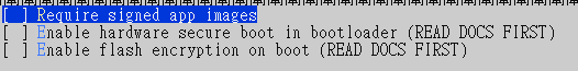
Make sure it look like this ,if there are '*' ,type space or 'N' to cancel it.
Exit and Save.
2.Run "idf.py menuconfig" AGAIN !! ,make sure your option has been saved.
3.Run "idf.py build"
4.Run "idf.py -p COMX flash"
5.Find your esptool.py location

This is my location.
6.Run "python esptool.py --chip esp32 --port com5 --baud 115200 --before default_reset --after hard_reset erase_flash"
7.Run "python espefuse.py -p com5 burn_efuse FLASH_CRYPT_CNT"
It will ask you to type "BURN",just do it.
8.Flash hello_world to test.
Sorry for my poor English .
 CJ0104
on 22 Jan 2020
CJ0104
on 22 Jan 2020
Hi @CJ0104 ,
Thanks for the advice but please note that flash read err, 1000 can have difference causes and following these steps may break the board not fix it.
Before running these steps run the command "espefuse.py -p PORT summary" and check the value of FLASH_CRYPT_CNT.
- If
FLASH_CRYPT_CNTvalue is 0, the error is unrelated to flash encryption and these steps might make it worse not better (by enabling flash encryption for no reason). - If
FLASH_CRYPT_CNTvalue is non-zero, following these steps may help by disabling flash encryption that was previously enabled via efuse but is not working correctly.
projectgus
on 22 Jan 2020
Thank you .
I'm so sorry about my comment.
I will try your advice.
Thank you so much.
And sorry for my poor English.
Angus Gratton notifications@github.com 於 2020年1月23日 週四 06:59 寫道:
Hi @CJ0104 https://github.com/CJ0104 ,
Thanks for the advice but please note that flash read err, 1000 can have
difference causes and following these steps may break the board not fix it
.Before running these steps run the command "espefuse.py -p PORT summary"
and check the value of FLASH_CRYPT_CNT.
- If FLASH_CRYPT_CNT value is 0, the error is unrelated to flash
encryption and these steps might make it worse not better (by enabling
flash encryption for no reason).- If FLASH_CRYPT_CNT value is non-zero, following these steps may help
by disabling flash encryption that was previously enabled via efuse but is
not working correctly.—
You are receiving this because you were mentioned.
Reply to this email directly, view it on GitHub
https://github.com/espressif/esp-idf/issues/113?email_source=notifications&email_token=AMVGBTKSICMSYGADU7YMQPDQ7DFULA5CNFSM4CW6RYH2YY3PNVWWK3TUL52HS4DFVREXG43VMVBW63LNMVXHJKTDN5WW2ZLOORPWSZGOEJVNGGI#issuecomment-577426201,
or unsubscribe
https://github.com/notifications/unsubscribe-auth/AMVGBTPOGNSV3DA6ZBWDUY3Q7DFULANCNFSM4CW6RYHQ
.
CJ0104
on 23 Jan 2020
I have tried changng fuses on these and don't recommend doin it because there's no way back if you screw up!
Get BlueMail for Android
On Jan 22, 2020, 7:09 PM, at 7:09 PM, CJ0104 notifications@github.com wrote:
Thank you .
I'm so sorry about my comment.
I will try your advice.
Thank you so much.And sorry for my poor English.
Angus Gratton notifications@github.com 於 2020年1月23日 週四 06:59 寫道:
Hi @CJ0104 https://github.com/CJ0104 ,
Thanks for the advice but please note that flash read err, 1000 can
have
difference causes and following these steps may break the board not
fix it
.Before running these steps run the command "espefuse.py -p PORT
summary"
and check the value of FLASH_CRYPT_CNT.
- If FLASH_CRYPT_CNT value is 0, the error is unrelated to flash
encryption and these steps might make it worse not better (by
enabling
flash encryption for no reason).- If FLASH_CRYPT_CNT value is non-zero, following these steps may
help
by disabling flash encryption that was previously enabled via
efuse but is
not working correctly.—
You are receiving this because you were mentioned.
Reply to this email directly, view it on GitHubhttps://github.com/notifications/unsubscribe-auth/AMVGBTPOGNSV3DA6ZBWDUY3Q7DFULANCNFSM4CW6RYHQ
.--
You are receiving this because you were mentioned.
Reply to this email directly or view it on GitHub:
https://github.com/espressif/esp-idf/issues/113#issuecomment-577445863
johncblacker
on 23 Jan 2020
One of the major problems with "fuses" is that changing the security fuse just adds 1 to the current value; then, when it's checked if it's an even number it means one thing and odd another. You cannot input a specific value for the security fuse (unless they've changed things recently).
johncblacker
on 23 Jan 2020
I was getting
rst:0x10 (RTCWDT_RTC_RESET),
boot:0x13 (SPI_FAST_FLASH_BOOT)
flash read err, 1000
ets_main.c 371
after only running app via CMAKE. Running flash wand rewriting the bootloader fixed it for me.
 seeul8er
on 10 Feb 2020
seeul8er
on 10 Feb 2020
 Kashyapkoshti
Related issues
 KaeLL
·
3Comments
KaeLL
·
3Comments
 okasha55
·
3Comments
okasha55
·
3Comments
 jakkubu
·
4Comments
jakkubu
·
4Comments
 ESP32DE
·
4Comments
ESP32DE
·
4Comments
 WayneKeenan
·
4Comments
WayneKeenan
·
4Comments
Most helpful comment
I know it is an old topic, bud the solution is simple. If you are getting:
Then it basicly tells you, it cant read from addres 0x1000, because that is apparently where it looks for bootloader or whatever. The solution is to set this offset when programming, so for my case it was:
And then after opening port at 115000bauds you get: