I was looking for ways to get rid of these to now avail.
Searched the web, Played with my Nvidia Ti750 driver's settings, Cura Shaders (C:\Program Files\Ultimaker Cura 3.2\resources\shaders\grid.shader) but can't get rid of this Moiré effect.
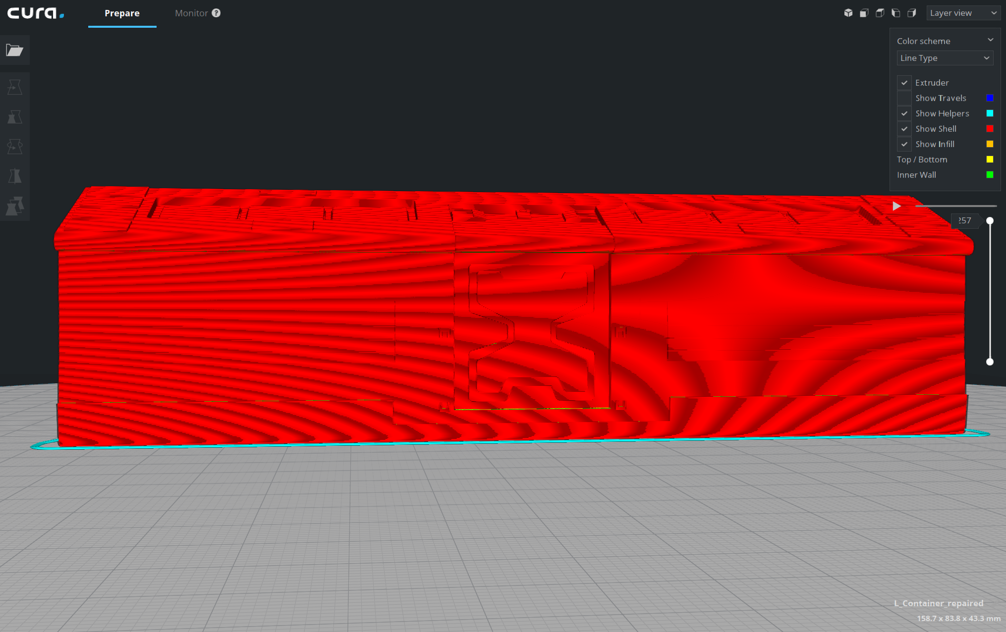
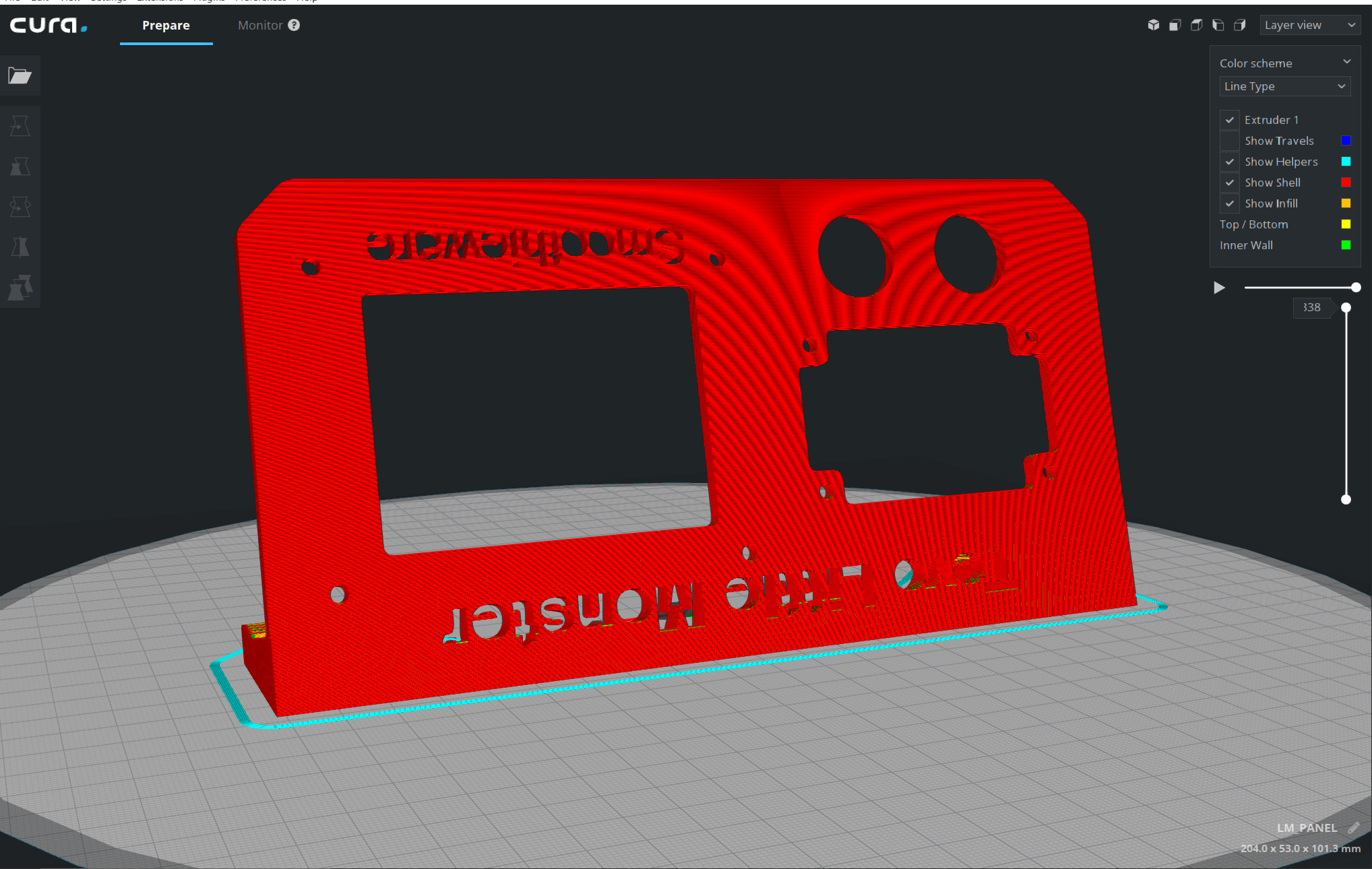
Any thoughts?
 Thisismydigitalself
All 20 comments
The obvious fix in my mind is to just not render the gcode as individual paths after a certain distance away from the model. Sure we could anti alias it but in this case that would be taking more processing power to achieve the same result: a flat red surface.
 ianpaschal
on 15 Feb 2018
ianpaschal
on 15 Feb 2018
Hi. From your post I understand I am not the only one who sees this. i thought there are settings to reduce this artifacts. at least i read in forums that users edited the shaders grid file which fixed it. i edited the file but the outcome is the same.
Thisismydigitalself
on 15 Feb 2018
The grid shader only influences the build plate grid. The moiré you see is in the model. It cannot be remedied easily (other than by zooming in)
 fieldOfView
on 15 Feb 2018
fieldOfView
on 15 Feb 2018
@fieldOfView It's the shaders that are rendering the lines as shaded "tubes" though, it's not actually tube geometry, right?
In this case the solution would be to, at certain distances, render the lines their basic lambertian color without a highlight or shadow, making the surface appear as a smooth surface.
Don't think that would be too much work. Whether or not it's something to put in the sprint... that I can't say.
ianpaschal
on 15 Feb 2018
The distance trick might actually work. I guess it would work as a rudimentary level of detail algorithm.
 nallath
on 15 Feb 2018
nallath
on 15 Feb 2018
At a certain moment I tried to set the opengl settings to super sample and similar things to that. The system wide settings concerning anti-alias etc didn't seem to influence Cura specific, and I also didn't manage to set super sampling or anti aliasing in Cura itself. It would be nice if we have some graphics settings like in games to set those things. The good thing is that we don't need to change the view itself, the downside is that you need a GPU with bigger balls.
@ianpaschal the tubes are "squared tubes", with their normals interpolated so they have a smooth view.
 jackha
on 15 Feb 2018
jackha
on 15 Feb 2018
@jackha Ah, Ok! that makes more sense why they look the way they do (not really round).
That does make my suggestion a little bit more tricky as I figured it was just a matter of switching shaders for the next frame where the camera is x distance from the origin.
But yeah, _might_ work.
ianpaschal
on 15 Feb 2018
Won't using the depth buffer solve it (eg; If it's further away than X, don't do the magic rendering)
nallath
on 16 Feb 2018
What do you mean by magic rendering?
Can't fall back to just "unshaded" as the model should still be shaded in terms of flat faces or else it will appear as a (in this case, red) silhouette.
ianpaschal
on 16 Feb 2018
The tubes are created in the shader, so it should be possible to not create tubes (but actual squares) if the distance is greater.
nallath
on 16 Feb 2018
The tubes are created in the shader
Ohhhhh! I thought from @jackha's comment that the lines were actually tube geometry. In that case, yes, this is fairly do-able.
ianpaschal
on 16 Feb 2018
The shader itself makes the tube geometry. I'm not a 100% sure how we do it, but from what I understood, we should be able to use different geometry shaders based on the depth buffer.
nallath
on 20 Feb 2018
we should be able to use different geometry shaders based on the depth buffer.
Yes. That would be my suggestion. I haven't looked at it but I imagine that the vertex shader is making more vertices (4) around each vertex n of the g-code lines in a vertical plane orientated to bisect the angle between vertices n-1 and n+1 (how convenient each layer's path is in a plane rather than floating around space!).
Basically you could use the depth buffer to blend between that shader's output and essentially solid view. Creating the solid view would be a bit of a trick though since. you'd have to recalculate virtual faces of the mesh based on the support g-code, in order to get them to have the right lighting and not just be bright (in this case) red.
ianpaschal
on 20 Feb 2018
A vertex-shader can't add more vertices; layerview uses a geometry shader (hence the "compatibility" fallback if geometry shaders are not available)
fieldOfView
on 20 Feb 2018
My take is that this would be best handles inside the fragment shader, which should blend between smooth shading or flat shading of the tubes created in the geometry shader, depending on the depth map.
fieldOfView
on 20 Feb 2018
A vertex-shader can't add more vertices;
Right. My mistake. Been a while since I wrote my own shader haha.
My take is that this would be best handles inside the fragment shader, which should blend between smooth shading or flat shading of the tubes created in the geometry shader, depending on the depth map.
Agreed, except flat shading the tube as "4 sided" instead of "round" will still cause moiré effects from the darker "under" and lighter "upper" sides of the square tube. Any idea how to handle that?
ianpaschal
on 20 Feb 2018
except flat shading the tube as "4 sided" instead of "round" will still cause moiré effects from the darker "under" and lighter "upper" sides of the square tube. Any idea how to handle that?
The moiré is going to be caused by layers in the y direction. You could just not use the y component of the normal for the (far-enough-away) shading.
fieldOfView
on 20 Feb 2018
I did a quick test like so:
diff --git "a/C:\\Users\\Aldo\\AppData\\Local\\Temp\\TortoiseGit\\layers3d-aed8fb8.000.shader" "b/C:\\Users\\Aldo\\Documents\\Code Projects\\UM\\Cura\\plugins\\SimulationView\\layers3d.shader"
index 03e279e..a434b04 100644
--- "a/C:\\Users\\Aldo\\AppData\\Local\\Temp\\TortoiseGit\\layers3d-aed8fb8.000.shader"
+++ "b/C:\\Users\\Aldo\\Documents\\Code Projects\\UM\\Cura\\plugins\\SimulationView\\layers3d.shader"
@@ -266,7 +266,11 @@ fragment41core =
         finalColor.rgb += f_color.rgb * 0.3;

         highp vec3 normal = normalize(f_normal);
+        normal.y = 0.5;
+        normal = normalize(normal);
         highp vec3 light_dir = normalize(u_lightPosition - f_vertex);
+        light_dir.y = 0.5;
+        light_dir = normalize(light_dir);

         // Diffuse Component
         highp float NdotL = clamp(dot(normal, light_dir), 0.0, 1.0);
This removes moiré on the sides of an object, but leaves a bit on the top. For best results it should be blended with the normal normals over distance.
fieldOfView
on 20 Feb 2018
I tried making it depend on this check:
u_modelViewProjectionMatrix * vec4(f_vertex, 0)).z > 1
But our zooming seems to be so weird that the view projection doesn't scale when you zoom out. You can try that with fieldOfView's trick of setting the Y-component of the normal vector to 0.5, but we'll have to find a better way for that as well.
Putting it in the geometry shader didn't work, as the model view projection matrix seems to not be initialised yet in the geometry shader (I was getting random data).
 Ghostkeeper
on 12 Mar 2018
Ghostkeeper
on 12 Mar 2018
I tried making it depend on this check:
u_modelViewProjectionMatrix * vec4(f_vertex, 0)).z > 1
But our zooming seems to be so weird that the view projection doesn't scale when you zoom out.
Uhm, by definition the projected coordinates will always be between -1 and 1. So that check is never going to work. You might have better results if you only transform by the model-view matrix, but then you will need some sort of "maximum distance" value.
Additionally, zooming is done through moving the camera, so the view matrix will indeed not scale, it will change its position instead.
Putting it in the geometry shader didn't work, as the model view projection matrix seems to not be initialised yet in the geometry shader (I was getting random data).
Geometry shaders expect transformed vertices, so the model-view-projection matrix is not by default exposed to the geometry shader. You'd need to expose it from the vertex shader to the geometry shader to get access to it.
 awhiemstra
on 12 Mar 2018
awhiemstra
on 12 Mar 2018
Related issues
 jellewie
·
3Comments
jellewie
·
3Comments
 timherrm
·
3Comments
timherrm
·
3Comments
 dstulken
·
3Comments
dstulken
·
3Comments
 rudowinger
·
3Comments
rudowinger
·
3Comments
 DmitryBychkov
·
3Comments
DmitryBychkov
·
3Comments