Im trying a simple deepsleep sketch to use it in one of my projects but when the deepsleep ends, the led flashes once and nothing happens. how can i fix this?
it sleeps because it doesnt print the deepsleep not working message but when its waking up, the led flashes once and nothing happens
I connected GPIO 16 to rst
i also debuged it with Serial.setDebugOutput(true);
Debug Messages
22:02:17.751 -> ets Jan 8 2013,rst cause:2, boot mode:(3,6)
22:02:17.751 ->
22:02:17.751 -> load 0x4010f000, len 1384, room 16
22:02:17.751 -> tail 8
22:02:17.751 -> chksum 0x2d
22:02:17.751 -> csum 0x2d
22:02:17.785 -> v8b899c12
22:02:17.785 -> ~ld
22:02:51.502 ->
22:02:51.502 -> ets Jan 8 2013,rst cause:2, boot mode:(3,6)
22:02:51.502 ->
my code:
include
void setup() {
Serial.begin(2400);
Serial.setDebugOutput(true);
}
void loop() {
// put your main code here, to run repeatedly:
Serial.print("Uaaah. I'm tired. Going back to bed for ");
Serial.println(" minutes. Good night!");
Serial.println("---");
ESP.deepSleep(20 * 1000000);
delay(100);
Serial.println("deepsleep not working");
}
 sntlyeet
All 125 comments
Just curious, why are you using such a slow baudrate for the serial port?
2400 bps is roughly about 240 characters per second.
Also the loop() function does not really run very long.
It is probably only awake for a few msec and then you don't have time to output anything to the serial port.
 TD-er
on 19 Jul 2019
TD-er
on 19 Jul 2019
Set the baud rate to 74400 and test again and post the new logfile if still required.
 fsommer1968
on 23 Jul 2019
fsommer1968
on 23 Jul 2019
Or maybe use Serial.flush(); after last print?
 suculent
on 25 Jul 2019
suculent
on 25 Jul 2019
I'm facing the same issue. I increased the baud rate to 74880, but the log doesn't show anything helpful. Any hints on this?
 bjoernbusch
on 26 Dec 2019
bjoernbusch
on 26 Dec 2019
@bjoernbusch Put a 1 to 2 second delay before you hit the ESP.deepSleep() command if you're doing something like the original poster. His code only runs for a few microseconds before it goes back into deep sleep, so the serial port never has a chance to get the first byte of his print statement sent out, and then the serial buffer is wiped when the chip resets and boots again after deep sleep. I ran deep sleep on a 30 minute cycle for a couple of months, so I know it works.
 Tech-TX
on 29 Dec 2019
Tech-TX
on 29 Dec 2019
Thanks, @Tech-TX it was actually an issue with the resistor between D0 and RST. Somehow my 560 resistor was too much, I replaced it by a simple wire and now it works.
bjoernbusch
on 29 Dec 2019
I was wrong about the delay(); I just pulled up my old test program and it works. I'm using a D1 Mini.
  // Deep sleep test for 5 seconds (5E6 microseconds) - the ESP8266 wakes up by itself if
  // GPIO16 (D0) is connected to the RESET pin or you press the RESET switch / ground RST.
  //
  // You'll need to ground GPIO0 (D3) and press the RESET switch to upload again after
  // this is running or the serial won't connect 'cos it's almost always ASLEEP.

void setup() {
  Serial.begin(74880);
//  while (!Serial) { } // Wait for serial to initialize (wasn't needed)
  Serial.println("I'm awake, but I'm going into deep sleep for 5 seconds");
}

void loop() {
  // your code goes here
    ESP.deepSleep(5E6); // good night!
    Serial.println("What... I'm not asleep?!?");  // it will never get here
}
Here's the output on the serial monitor:
ets Jan 8 2013,rst cause:2, boot mode:(3,6)
load 0x4010f000, len 3456, room 16
tail 0
chksum 0x84
csum 0x84
v3197d2ac
~ld
I'm awake, but I'm going into deep sleep for 5 seconds
I only get down to about 17mA current draw during Deep Sleep with my D1 Mini due to the horrid linear regulator used on this cheap clone board plus the CH340 UART <> USB chip. A Holtek HT7833 regulator would get lower as the quiescent current is better on their parts.

Tech-TX
on 29 Dec 2019
Per @Tech-TX:
Closing due to unable to reproduce.
 devyte
on 29 Dec 2019
devyte
on 29 Dec 2019
@Tech-TX, @devyte: Today I received a batch of Wemos D1 mini's and two of them failed to wake-up as well. I tried different resistor values and wires between D1 (GPIO15) and RST, but did not make sense.
After a lot of wasting time, I found this interesting thread:
https://github.com/esp8266/Arduino/issues/6007#issuecomment-542192213
With this sketch I'm able to wake the Wemos D1 mini:
#include "ESP8266WiFi.h"
extern "C" {
#include <user_interface.h>
}

#define ets_wdt_disable ((void (*)(void))0x400030f0)
#define ets_delay_us ((void (*)(int))0x40002ecc)

#define _R (uint32_t *)0x60000700


void nk_deep_sleep(uint64_t time)
{
    ets_wdt_disable();
    *(_R + 4) = 0;
    *(_R + 17) = 4;
    *(_R + 1) = *(_R + 7) + 5;
    *(_R + 6) = 8;
    *(_R + 2) = 1 << 20;
    ets_delay_us(10);
    *(_R + 39) = 0x11;
    *(_R + 40) = 3;
    *(_R) &= 0xFCF;
    *(_R + 1) = *(_R + 7) + (45*(time >> 8));
    *(_R + 16) = 0x7F;
    *(_R + 2) = 1 << 20;
    __asm volatile ("waiti 0");
}

void setup()
{
    delay(1000);

    nk_deep_sleep(2000000);
}

void loop()
{
}
However, I've no idea about the internals and how to wake with or without RF enabled. According to the thread, it looks like an issue with newer ESP-12F. Do you have more information on this?
 Erriez
on 9 Oct 2020
Erriez
on 9 Oct 2020
No new info. The only 2 known workarounds are the code above and the 47K pullup on MISO, and even that doesn't help all cases.
It would be interesting if somebody could reverse engineer the sdk deep sleep calls and figure out the difference vs the above code, especially the wakeup param. We could then implement our own version of deep sleep.
devyte
on 10 Oct 2020
@devyte, I agree. And I think the person to do it is @nikolz0. He wrote that function above. Problem is, nk_deep_sleep consumes ~2mA after cutting the LDO and UART 3V3 trace, so it's nowhere near "deep sleep". If anything, nikolz0 has created a working "light sleep'. I'm trying to pick their brain to comment the code so we know whats happening, and if they have time, try and figure out the modification required to make it go "deep"
 studioant
on 10 Oct 2020
studioant
on 10 Oct 2020
@Erriez , according to the author, the line *(_R + 4) = 0; disables WiFi.
In light of this information the author has provided, we can assume this person is certainly capable of solving this issue once and for all. We need this hero in our lives
studioant
on 10 Oct 2020
@studioant that sounds like some pull-up resistor somewhere to me. Or a resistor voltage divider.
devyte
on 10 Oct 2020
@devyte You might be right, I found this Mux Register info:

I'm not sure what the hex should be for "Pull-down during sleep" but it looks like somewhere after 0x60000804.
This is on esp8266 wiki: https://github.com/esp8266/esp8266-wiki/wiki/Memory-Map

@nikolz0 defines his register variable _R starting at this hex value, so he's manipulating the RTC config registers, but i can't find the register doc on this... where's the include/eagle_soc.h header file?
studioant
on 10 Oct 2020
Thanks for looking into this. I checked my stock and discovered multiple ESP8266 chips which does not wake up after deep sleep.
@studioant You're right: The current consumption is 2.5mA with the magic workaround sketch. That explains why my batteries are drained quickly... :cry:
@devyte
It would be interesting if somebody could reverse engineer the sdk deep sleep calls and figure out the difference vs the above code, especially the wakeup param. We could then implement our own version of deep sleep.
I'd like to summarize some facts about this issue, because I found a lot of wrong assumptions and discussions on other threads:
- This problem has been reported on newer ESP12F chips only.
- This repository uses the latest Espressif NONOS SDK version "2.2.2-dev(38a443e)", but needs volunteers to port it to the latest NONOS SDK version 3.0.2.
Please correct me if I'm wrong.
Did someone already try the latest NONOS SDK version 3.0.2 to see if deepSleep works?
Erriez
on 10 Oct 2020
Hi, try downloading this test from the address 0x0000, terminal 74880, deepsleep 12 sec.
 nikolz0
on 10 Oct 2020
nikolz0
on 10 Oct 2020
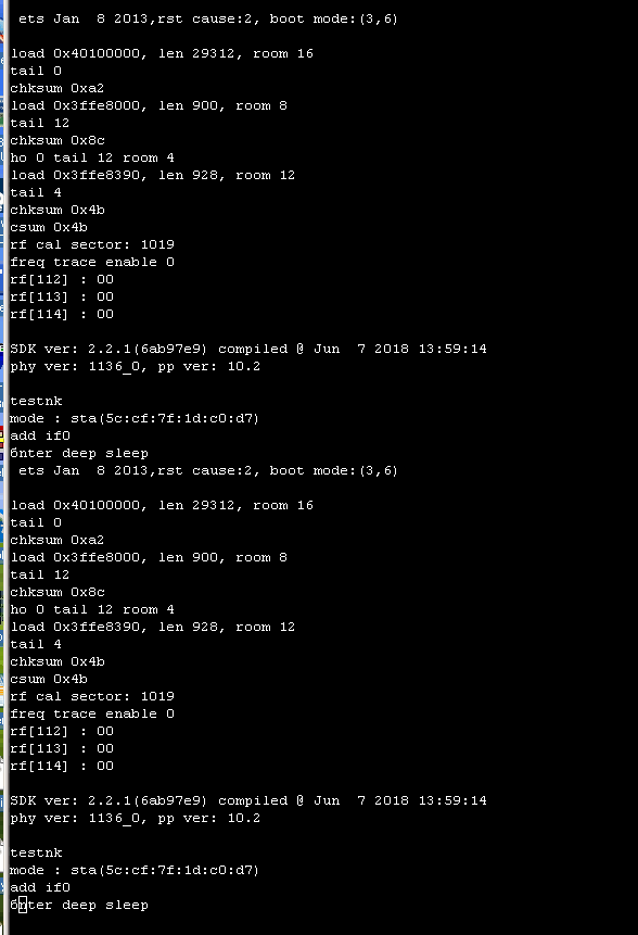
@nikolz0 The output is:
 ets Jan  8 2013,rst cause:2, boot mode:(3,7)

load 0x40100000, len 580, room 16
tail 4
chksum 0x62
load 0x3ffe8004, len 268, room 4
tail 8
chksum 0x2e
csum 0x2e

testnk deepsleep

...
Same output after 12 seconds reset
It resets every ~12 seconds and the power consumption is 170uA (same to other WeMos D1 Mini's)... Eh... this sounds promising. Can you share the contents of this bin?
Erriez
on 10 Oct 2020
Hi,
This is code without the SDK, only the deepsleep function . Made for checking ESP.
You can do the same in your program using the SDK function
system_deep_sleep_instant(12000000);
In the user_init function, call
system_deep_sleep_set_option(2);
nikolz0
on 10 Oct 2020
* This repository uses the latest Espressif NONOS SDK version "2.2.2-dev(38a443e)", but needs volunteers to port it to the latest NONOS SDK version 3.0.2.Arduino for 8266 does not support NONOSSDK 3.x, there is a long thread in the issues section about this.
fsommer1968
on 10 Oct 2020
@Erriez you are correct: we're still on NONOS sdk 2.x, and we want to migrate to 3.x. We've had a few attempts, but walls have been hit. Volunteers in this case means either someone who has a deeper understanding of how our core interfaces with the sdk, or someone who is willing to stick around long term and aquire that understanding in time.
I outlined somewhere what I think needs to be done at high level.
devyte
on 10 Oct 2020
@nikolz0
This is code without the SDK, only the deepsleep function .
I don't know how to build it without SDK. In my understanding include file user_interface.h is always required to access the Espressif SDK, right?
In the user_init function, call
system_deep_sleep_set_option(2);
For this repository, I found a preinit() function which is called from user_init() and added the system_deep_sleep_instant(12000000); to setup().
It wakes up twice as I encountered before:
extern "C" {
#include "user_interface.h"

void preinit() {
    system_deep_sleep_set_option(2);
}
}

void setup() {
    // Does not wake:
    system_deep_sleep_instant(12000000);
}

void loop() {
}
Output:
 ets Jan  8 2013,rst cause:2, boot mode:(3,6)

load 0x4010f000, len 3584, room 16
tail 0
chksum 0xb0
csum 0xb0
v2843a5ac
~ld

 ets Jan  8 2013,rst cause:2, boot mode:(3,6)

No further resets...
The load ... is missing in the serial output and looks like not starting the sketch.
Any Idea?
Erriez
on 10 Oct 2020
@Tech-TX, @devyte: Today I received a batch of Wemos D1 mini's and two of them failed to wake-up as well. I tried different resistor values and wires between D1 (GPIO15) and RST, but did not make sense.
After a lot of wasting time, I found this interesting thread:
#6007 (comment)
...
However, I've no idea about the internals and how to wake with or without RF enabled. According to the thread, it looks like an issue with newer ESP-12F. Do you have more information on this?
@Erriez I read reports over on esp8266.com about Deep Sleep 'zombie mode', but never saw it here at home. Where did you get the D1 Mini boards from? I'd like to be able to duplicate your results here.
For the GPIO16 > RST connection I use either a Schottky or germanium diode. The cathode of the diode (the stripe) goes to GPIO16, and the anode goes to RST. Using a resistor could effect the pulse getting to the RST line of the CPU, and exactly what it does depends on what they've done underneath the can on the ESP-12F. I've seen 4 different RF shields from different companies in China, including one that has copied the Lolin logo (although I doubt Lolin made them.) In one thread I read someone removed the RF shield and found a resistor in series between the RST pin on the module and the RST pin on the CPU. Doing that can cause problems, especially if you're using a resistor to connect GPIO16 to RST. The actual reset pulse might get attenuated to the point where the chip won't see it.
Tech-TX
on 11 Oct 2020
@Tech-TX , The issue is clearly deeper than this, you even commented in February in the original thread.
In one thread I read someone removed the RF shield and found a resistor in series between the RST pin on the module and the RST pin on the CPU.
Yeah, the thread you literally included in this comment? There are even recorded attempts (in said thread) to remove the resistor, bypass it, etc to no avail. Obviously, not gonna help.
@nikolz0 explained it in that thread, plus he created a (almost spot-on) solution. It just needs further enhancement, atm it's allowing the ESP to draw too much current during deep sleep (I understand you have recorded lower current draw, but I have now recorded 2mA consistently across several bare-bone ESP's )
@nikolz0 - Do you have a copy of the RTC register manual? I can't seem to find it anywhere. It would be great to understand better what your function is doing. TIA
studioant
on 11 Oct 2020
Hi,
I connect the GPIO16 and RST using a Schottky diode.
So I have no problem with the versions of the ESP-12.
nikolz0
on 11 Oct 2020
Hi,
Are you using Wemos or ESP-12?
is testnk working correctly?
testnk.zip
There is an automatic mode "vemos" control. I believe that it interferes with deep sleep mode.
I write in C, but I'll try to tell you something.
try this:
`
include
void setup() {
Serial.begin(115200);
Serial.setTimeout(1000);
while(!Serial) { }
}
void loop() {
Serial.println("Test");
delay(1000);
ESP.deepSleep(12000000);
}
`
nikolz0
on 11 Oct 2020
nikolz0
on 11 Oct 2020
I'm not sure what you're linking to @nikolz0 as I think that thread has been resolved.
If there's a specific post that's relevant, you can pick it with the three dots to the right of the post title bar,

Tech-TX
on 11 Oct 2020
FWIW if I run nicolz0's test binary it works as expected, and I get around 15uA sleep current.
If I run that test code that Erriez linked above it only sleeps for 1.4ms, no matter what I set 'time' to in the nk_deep_sleep(time) call. It's sleeping so briefly that I can'[t measure the current, but it looks like it's on the order of 2 to 4mA.
Tech-TX
on 11 Oct 2020
@Tech-TX
@Erriez I read reports over on esp8266.com about Deep Sleep 'zombie mode', but never saw it here at home. here did you get the D1 Mini boards from? I'd like to be able to duplicate your results here.
I've purchased multiple batches from different shops and I did not mark them. My last batch came from Aliexpress Sincere Company Store Wemos D1 Mini.
Only one of them cannot wake after deepsleep, others work as expected. I cannot find any differences in PCB, so it is concerning that nobody knows which version will be shipped.
The cathode of the diode (the stripe) goes to GPIO16, and the anode goes to RST
I could not get it stable with different resistors and germanium diode as you suggested. A software solution would be appreciated and testnk.bin is the evidence that this is not hardware related, just by using a simple wire between GPIO15 and RST.
@studioant There are different deepsleep issues, but I could not find a solution for this problem.
@nikolz0
Are you using Wemos or ESP-12?
Yes, this is a Wemos ESP12F D1 Mini (lite) with 4MB flash. That's the reason why I posted on this thread, but seems more related to newest ESP12F batches.


is testnk working correctly? testnk.zip
Yes, the testnk is the only binary which works on my device with a simple 0 Ohm wire between RST and GPIO16 (D1) Update: (D0): Wake works and 170uA in deep sleep. So now I'd like to know how to port this to my application by using this repository.
There is a magic difference between your binary which works and ESP.deepSleep(12000000); in this repository which does not work on several of my devices:
SDK version: 2.2.2-dev(a58da79)
Wake

 ets Jan  8 2013,rst cause:2, boot mode:(3,6)

=> Does not start the sketch.
I'll hookup my scope to measure the RST pulse and measure the current...
Erriez
on 11 Oct 2020
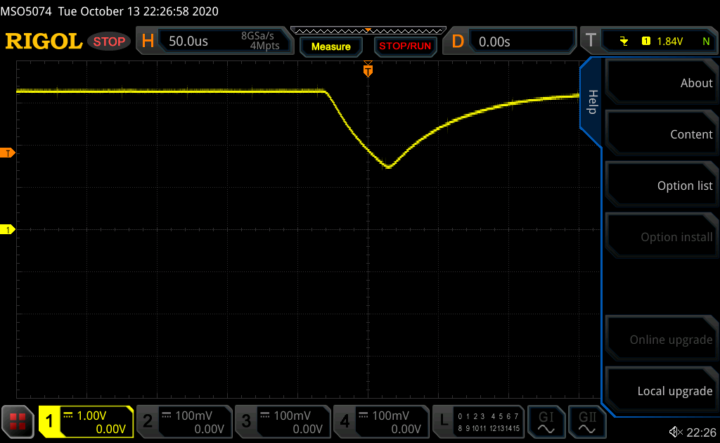
The wake RST pulse length for all devices and tests is 50us with a wire:
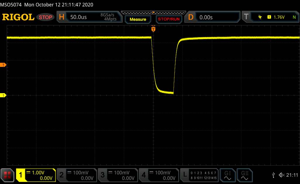
The timing changes when replacing the wire with a diode or resistor, but none of them works.
- Working board 1: Wake works with ESP.deepsleep():
- 68mA vs 150uA.
ets Jan 8 2013,rst cause:2, boot mode:(3,6)load 0x4010f000, len 3584, room 16
- Wake problem board 2: Wake does not work with ESP.deepsleep():
- 68mA vs 20mA.
ets Jan 8 2013,rst cause:2, boot mode:(3,6)No output
- Wake problem board 2: Wake works after flashing
testnk.bin:
- 69mA vs 119uA
ets Jan 8 2013,rst cause:2, boot mode:(3,7)load 0x40100000, len 580, room 16
@nikolz0 @Tech-TX I'm curious about the differences between the testnk.bin and ESP.deepsleep() in this repository...
Do you have any suggestions I can try / measure?
Erriez
on 11 Oct 2020
I can't tell what is inside testnk.bin; perhaps nikolz0 would post the source, No way to tell you how it's different from ESP.deepsleep(). If I had the elf for it I could run a disassembly of it. but that's a painful task since the disassembly frequently gets out of sync and starts puking up junk. From the size of his file, it's assembly or compiled (something) without the SDK.
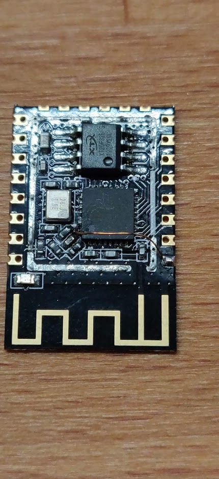
I've seen people selling those ESP-12F modules you showed above, but with no vendor name and a (likely) forged copy of the Espressif logo on the RF can I always avoided them. All of mine are either DOIT or AI Thinker, and those work fine. I haven't tried any of DOIT's newer modules labeled DOITING, but I've heard of problems with them.
The RST pulse you're showing is on the module pin, not inside on the chip, correct? With a (possible) series resistor inside the RF shield, all bets are off on what it looks like at the chip. It may be shorter duration and may not hit 0V; it depends on what's under the can. A series resistor will mess up the RST pulse.
The reason I use a Schottky or germanium diode is because the RTC puts GPIO16 in OUTPUT mode when you're in Deep Sleep. If you externally pull RST low you're shorting the GPIO16 output to ground. With a diode it's protected.
With the LDO and CH340G installed, most of my modules run around 6mA during Deep Sleep. If I cut them off, it drops to 16uA during Deep Sleep. The LDO on my boards is marked 4A2D (no logo), which could be Torex or more likely one of the no-name Chinese clone parts. The CH340G _looks_ like a real QinHeng part, but I know there are clones of it.
Your module looks like a D1 Mini, but it isn't Wemos (no 'WeMos.cc' name on it) so it's a clone. I've seen a genuine Wemos board and it had the Wemos name.
@Erriez in your first post you said:
"I tried different resistor values and wires between D1 (GPIO15) and RST," That's a typo, right? You'll never wake the CPU trying to drive it with GPIO15, only with GPIO16 (D0). Pin sequence on that side is RST, A0, D0, D5, D6, D7, D8, 3V3.
Absolutely relevant previous issue: https://github.com/esp8266/Arduino/issues/6007
He also had ESP-12F modules with an Espressif logo on them.
My only observation on that thread is on petrilloa's first post: I can't find any manufacturer ID of 0x0E for the flash. Other than that, it looks like there may be 4 different problems discussed that cause 'zombie mode': 1) bad PSU, 2) bad flash, 3) auto-program circuit engaging at boot, and 4) whatever pulling up MISO might be.
Tech-TX
on 12 Oct 2020
Hi, put not just a diode, but a Schottky SS14 diode.
Connect the cathode to GPIO16.
Do not set the pull-up resistor to RST.
nikolz0
on 12 Oct 2020
Hi,
this test uses the SDK_2.2.1. Address 0x00000,0x10000, terminal 74880.
Wemos. The RTS connects to the gpio16 via a resistor. Work normally.
testnkSDK.zip
nikolz0
on 12 Oct 2020
Hi,
this test uses SDK_3.05. address 0x00000, 0x10000, terminal 74880.
testnk_SDK_305.zip
nikolz0
on 12 Oct 2020
Here's the schematic for the AI Thinker ESP-12F, from their a014ps01 V1.pdf:

Note the series resistor (R3) on RST at the upper right
Tech-TX
on 12 Oct 2020
@Tech-TX
If I run that test code that Erriez linked above it only sleeps for 1.4ms, no matter what I set 'time' to in the nk_deep_sleep(time) call. It's sleeping so briefly that I can'[t measure the current, but it looks like it's on the order of 2 to 4mA.
Correct, the power consumption of that skatch is too high for battery usage. So that's not a solution.
The RST pulse you're showing is on the module pin, not inside on the chip, correct?
Correct. this is measured at the RST pin and wire to GPIO16 D0.
With a (possible) series resistor inside the RF shield, all bets are off on what it looks like at the chip. It may be shorter duration and may not hit 0V; it depends on what's under the can. A series resistor will mess up the RST pulse.
So next step would be to remove the shield and measure strait with a scope on the ESP8266EX XPD_DCDC pin 8?
It may be shorter duration and may not hit 0V;
I've doubts that we are looking at a hardware issue, because testnk.zip in https://github.com/esp8266/Arduino/issues/6318#issuecomment-706560461 works flawless without SDK, but it is a binary...
Note: I posted one scope picture of the RST pulse, but the signal is identical to another working board.
I tried different resistor values and wires between D1 (GPIO15) and RST,
Good catch, that's a typo. I've updated the comment.
If you externally pull RST low you're shorting the GPIO16 output to ground. With a diode it's protected.
Aha, now I understand the function of this diode.
He also had ESP-12F modules with an Espressif logo on them.
Interesting. Is Espressif the only manufacture of the ESP8266EX chip, or are their counterfeit chips on the market? It becomes a big problem nowadays.
Your module looks like a D1 Mini, but it isn't Wemos (no 'WeMos.cc' name on it) so it's a clone.
Yes, only clones left since WeMos.cc stopped selling it. The quality of the blue PCB and soldering is good. I'm not sure who manufactures the ESP8266 (small PCB with antenna). I considered to desolder this board from the blue PCB to exclude hardware problems, but I don't have the right equipment to do this. Now I see that there are some components under the shield. A strait forward schematic of the AI Thinker, but not sure if this matches with mine.
With the LDO and CH340G installed, most of my modules run around 6mA during Deep Sleep.
I must say that the deep sleep of the working boards without modifications is around 170uA which is good. I also measured around 4..6 mA with NodeMCU's.
If I cut them off, it drops to 16uA during Deep Sleep.
A while ago I did the same, but it was hard to find the right trace as there are different Wemos D1 Mini PCB's.
The LDO is a DE=A1D. (Thanks to my cellphone microscope)
The mounted CH340G is stable with flashing at 3000000, so I think it's a genuine one:
Bus 002 Device 091: ID 1a86:7523 QinHeng Electronics HL-340 USB-Serial adapter
idVendor:  0x1a86 QinHeng Electronics
idProduct: 0x7523 HL-340 USB-Serial adapter
MAC STA AP: C8:2B:96:2F:8E:C6
Is a known Espressif MAC address: https://www.adminsub.net/mac-address-finder/espressif
With only 10 business days shipping to The Netherlands, it may be an idea to buy a few samples from Sincere.
I think I've answered your questions, otherwise let me know. Next post I'll show the zip results.
Erriez
on 12 Oct 2020
@nikolz0
put not just a diode, but a Schottky SS14 diode.
Unfortunately I don't have Schottky diods on stock, so I tried a germanium diode as @Tech-TX suggested.
testnkSDK
Thanks for the binaries. I've flashed:
- 0x00000 for eagle.flash.bin
- 0x10000 for eagle.irom0text.bin
With or without a wire or diode, the CPU resets every 166ms. Maybe I do something wrong.
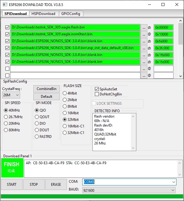
This is the same for testnk_SDK_305. Screenshot download tool:
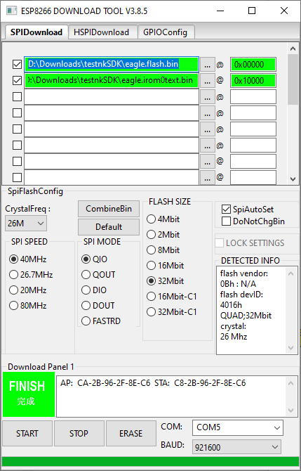
Did I configure it incorrectly, or miss a binary?
Erriez
on 12 Oct 2020
Hi,
message rf_col[0]!=0x05 indicates
that you have incorrectly loaded the default system settings.
nikolz0
on 12 Oct 2020
Ok, I've restored the AT commands first from https://github.com/espressif/ESP8266_NONOS_SDK/releases/tag/v3.0.4

AT commands works. AT instruction set
Then flash testnkSDK:
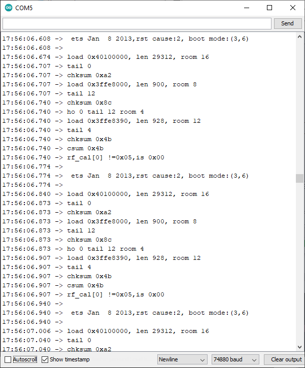
 ets Jan  8 2013,rst cause:2, boot mode:(3,6)

load 0x40100000, len 29312, room 16
tail 0
chksum 0x7d
load 0x08005210, len 1146759052, room 8

===> No reset pulse generated on GPIO16
Then flash testnk_SDK_305:
20:57:19.130 ->  ets Jan  8 2013,rst cause:2, boot mode:(3,7)
20:57:19.130 ->
20:57:19.196 -> load 0x40100000, len 31216, room 16
20:57:19.229 -> tail 0
20:57:19.229 -> chksum 0x4a
20:57:19.229 -> load 0xd8b10800, len 769779921, room 8
... 4 seconds delay
20:57:23.249 -> flash read err, ets_unpack_flash_code
20:57:23.249 -> ets_main.c
@nikolz0 Do you know what flash read err, ets_unpack_flash_code means?
Erriez
on 12 Oct 2020
1) bad PSU,
Excluded: Same problem with external 3V3 power supply and capacitors.
2) bad flash,
Excluded: Flashing works reliable.
3) auto-program circuit engaging at boot,
Excluded with external FTD232 programmer.
4) whatever pulling up MISO might be.
Excluded: I tried a 47k pull-up on D6 MISO
5) Unknown yet...
Erriez
on 12 Oct 2020
I've successfully removed the shield and measured directly on the nRST pin as you suggested.
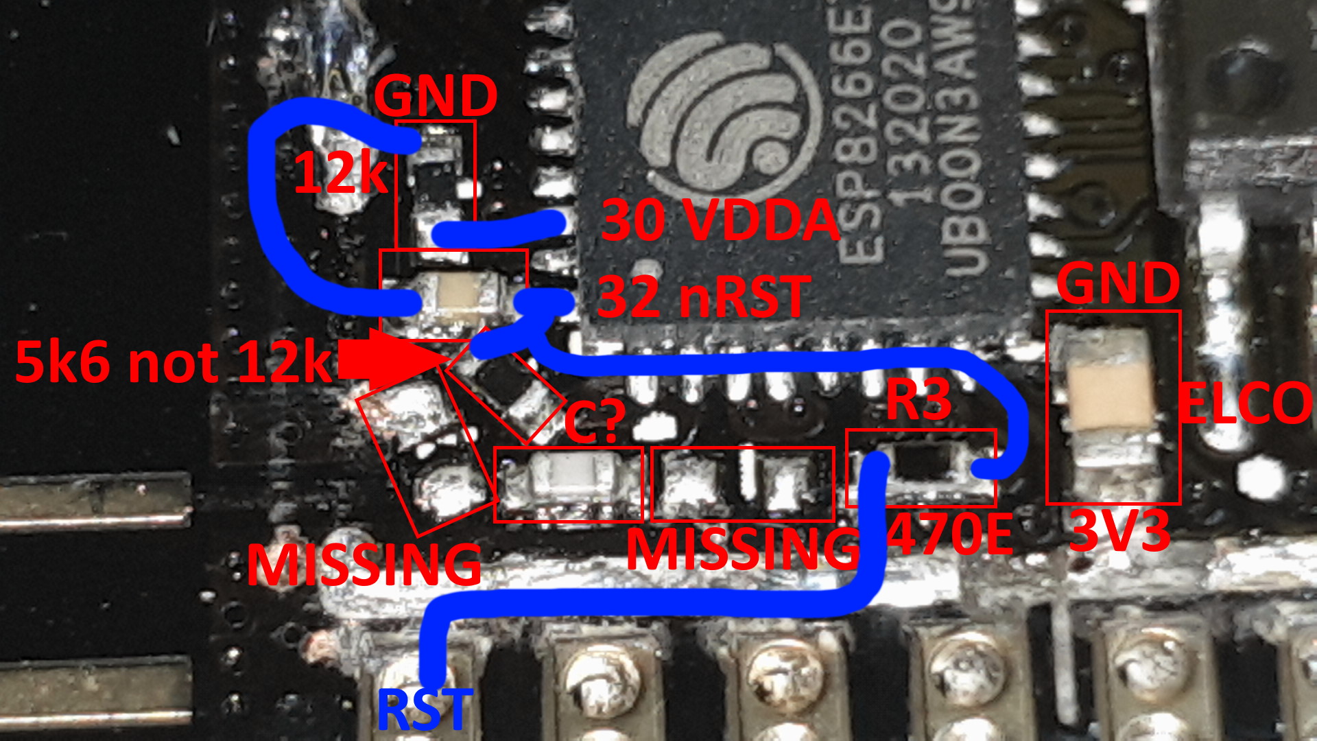
As you can see, two components are missing. (No idea if they are needed). I also noticed that pull-up resistor R2 on nRST is 5k6 instead of 12k! I see the evidence on the scope on pin 32 nRST:
This is the first time I'm convinced that nRST is not pulled low enough after ESP.deepSleep().
Hmm... I'm thinking how to replace this tiny SMD...
Erriez
on 12 Oct 2020
@nikolz0 вы знаете, что
flash read err, ets_unpack_flash_codeэто значит?
Hi,
This happens for two reasons.
1) faulty flash;
2) ESP in sleep mode. To get the ESP out of sleep mode, I write using the nodemcuflasher blank.bin, address 0x0000.
When writing esp_init......bin, 0x3fc000 should be used instead of 0x1fc000.
nikolz0
on 12 Oct 2020
Hi,
what will be the pulse if you put a diode between RST and GPIO16?
According to your photo it turns out that 470 ohms is enabled between the nRST pin and the external RST pin?
If this is the case, then connect RST and GPIO16 should be a conductor, not a resistor.
nikolz0
on 12 Oct 2020
@Erriez I think your reset is fine... it goes HIGH when the chip acknowledges the RST and releases the low on GPIO16. As I'd mentioned elsewhere, I can't track inside the reset detection code, but that 'release GPIO16' could be either in the RTC hardware or the reset logic in the boot code. In either case, it's successfully come out of Deep Sleep.
If you're getting the "rst cause:2, boot mode:(3,6)" boot message but not the following LOAD message, then I'm in agreement with nikolz0: it might think it's getting a LOW on GPIO0 and is going into FLASH mode, and not RUN. Check the level on GPIO0 (and maybe GPIO2) when it gets that reset pulse, if you would? I doubt GPIO15 is pulling up high, and also doubt TX being pulled LOW. If it's in FLASH mode, you should be able to query it with esptool (see below).
If you get a message about 'ets_main.c' then it is likely that you have noise on CH_PD. There's a bug in the reset detection code, and it goes off (somewhere) in the SDK if it thinks it saw CH_PD low after Deep Sleep is called.
Another thing you can try is to kill the modem during the boot. I have some code here that'll minimize boot current to 35mA average, 54mA peak. That could have an effect two different ways on the issue you're seeing, although it's less likely to help if you never get the LOAD message as the RF_PRE_INIT() is already after it's decided to load/flash/selftest.
You could still have funky flash. There's some flash detection (in boot?) that tries to figure out how to proceed (DOUT, DIO, QOUT, QIO) and it's possible that one of those mysterious writes of nikolz0' to the RTC registers stops that or locks it in one of the workable flash modes. It'd take me quite a while to test each write to see if I can detect what they're doing to the CPU, and some of those writes I'd never guess. If you have manufacturer ID = 0x0E like the other gentleman, then I have NO clue what that flash chip is.
esptool.py -p /dev/ttyUSB0 flash_id (linux)
esptool.py -p COMx flash_id (Windows, where 'x' is your COM port)
(has to be in flash programming mode, of course!)
Unfortunately I don't have Schottky diods on stock, so I tried a germanium diode as @Tech-TX suggested.
(laughs) Either you're an old fart like me or an RF geek. Most folks today have never SEEN a germanium.
Your LDO is either one of these two or a Chinese clone:
http://www.txsemi.com/Upload/TX6211B_V12-11264794020.pdf
https://www.richtek.com/assets/product_file/RT9193/DS9193-17.pdf
If it's a clone, all bets are off on the part specifications. It SHOULD be able to handle 300mA.
He also had ESP-12F modules with an Espressif logo on them.
Interesting. Is Espressif the only manufacture of the ESP8266EX chip, or are their counterfeit chips on the market? It becomes a big problem nowadays.
What I was describing was the Espressif logo on the RF can. As far as I know, Espressif doesn't make ESP-12F modules, only the '8266 WROOM modules. In the US it's illegal to use someone's logo without their permission. It's also illegal to use that FCC symbol without a certificate; only AI Thinker and DOIT have certs that I'm aware of for the -12F module. When I saw that combination on the RF shield (surfing eBay) I immediately hit the BACK key 'cos I knew the boards were wonky. I also avoid the modules with NO vendor mark on them. Weird, illegal markings or NO marking is a sign it's not a good bet for my money.
Tech-TX
on 13 Oct 2020
@nikolz0
ESP in sleep mode. To get the ESP out of sleep mode, I write using the nodemcuflasher blank.bin, address 0x0000.
Oh, that makes sense. I've flashed with https://github.com/nodemcu/nodemcu-flasher
testnk_SDK_305.zip from https://github.com/esp8266/Arduino/issues/6318#issuecomment-706845183
- 0x00000 eagle.flash.bin
- 0x10000 eagle.irom0text.bin
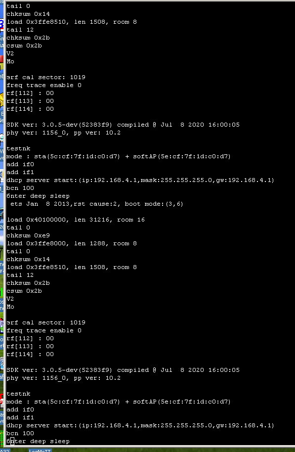
8:04:17.410 ->  ets Jan  8 2013,rst cause:2, boot mode:(3,6)
18:04:17.410 ->
18:04:17.410 -> load 0x40100000, len 31216, room 16
18:04:17.443 -> tail 0
18:04:17.443 -> chksum 0xe9
18:04:17.443 -> load 0x3ffe8000, len 1288, room 8
18:04:17.443 -> tail 0
18:04:17.443 -> chksum 0x14
18:04:17.443 -> load 0x3ffe8510, len 1508, room 8
18:04:17.477 -> tail 12
18:04:17.477 -> chksum 0x2b
18:04:17.477 -> csum 0x2b
18:04:17.477 -> V2
18:04:17.477 -> Mo
18:04:17.510 -> ⸮rf cal sector: 1019
18:04:17.510 -> freq trace enable 0
18:04:17.543 -> rf[112] : 00
18:04:17.543 -> rf[113] : 00
18:04:17.543 -> rf[114] : 01
18:04:17.543 ->
18:04:17.543 -> SDK ver: 3.0.5-dev(52383f9) compiled @ Jul  8 2020 16:00:05
18:04:17.543 -> phy ver: 1156_0, pp ver: 10.2
18:04:17.543 ->
18:04:17.543 -> testnk
18:04:17.543 -> mode : softAP(ca:2b:96:2f:8e:c6)
18:04:17.543 -> add if1
18:04:17.543 -> dhcp server start:(ip:192.168.4.1,mask:255.255.255.0,gw:192.168.4.1)
18:04:17.576 -> bcn 100
18:04:17.576 -> enter deep sleep
⸮⸮
18:04:27.311 ->  ets Jan  8 2013,rst cause:2, boot mode:(3,6)
18:04:27.311 ->
No further output with a wire between RST and D0.
what will be the pulse if you put a diode between RST and GPIO16?
The pulse length is much longer now (with 1ms per division), measured on ESP8266EX pin 32 nRST with a 1N4148 between RST and D0:

According to your photo it turns out that 470 ohms is enabled between the nRST pin and the external RST pin?
Yes, a 470 Ohm resistor is located between RST pin and nRST.
If this is the case, then connect RST and GPIO16 should be a conductor, not a resistor.
Correct.
Erriez
on 13 Oct 2020
@Tech-TX
In either case, it's successfully come out of Deep Sleep.
Yes, it wakes from deepsleep only once, but does not start the sketch.
Check the level on GPIO0 (and maybe GPIO2) when it gets that reset pulse, if you would? I doubt GPIO15 is pulling up high, and also doubt TX being pulled LOW. If it's in FLASH mode, you should be able to query it with esptool (see below).
The Wemos D1 Mini has a 10k pull-up resistor on GPIO0 (D3) and GPIO2 (D4).
#include <user_interface.h>

#define _R (uint32 *)PERIPHS_RTC_BASEADDR
#define valRTC 0xFE000000  // normal value during CONT (modem turned on)

RF_PRE_INIT() {
  *(_R + 4) = 0;  // value of RTC_COUNTER for wakeup from light/deep-sleep (sleep the modem)
  system_phy_set_powerup_option(2);  // stop the RFCAL at boot
  wifi_set_opmode_current(NULL_MODE);  // set Wi-Fi to unconfigured, don't save to flash
  wifi_fpm_set_sleep_type(MODEM_SLEEP_T);  // set the sleep type to Forced Modem Sleep
  // moving the two SDK commands up here saves another 670us @ 8 mA of boot current :-)
}

void preinit() {
  *(_R + 4) = 0;  // sleep the modem again after another initialize attempt before preinit()
  wifi_fpm_open();  // enable Forced Modem Sleep, not in RF_PRE_INIT or it doesn't sleep
  wifi_fpm_do_sleep(0xFFFFFFF);  // enter Modem Sleep mode, in RF_PRE_INIT causes WDT
  // won't go into Forced Modem Sleep until it sees the delay() in setup()
}

void setup() {
  Serial.begin(74880);
  Serial.println("Wake");
   *(_R + 4) = valRTC;  // Force Modem Sleep engaged, set the modem back to 'normal' briefly
  delay(1000);  // and sleep the modem at 18mA nominal substrate current
  ESP.deepSleep(2000000);
}

void loop() {
}
20:34:57.507 ->  ets Jan  8 2013,rst cause:2, boot mode:(3,6)
20:34:57.507 ->
20:34:57.507 -> load 0x4010f000, len 3584, room 16
20:34:57.507 -> tail 0
20:34:57.507 -> chksum 0xb0
20:34:57.507 -> csum 0xb0
20:34:57.541 -> v2843a5ac
20:34:57.541 -> ~ld
20:35:21.800 ->
20:35:21.800 ->  ets Jan  8 2013,rst cause:2, boot mode:(3,6)
20:35:21.800 ->

===> No output, it does not print the "Wake" string.
Chip ID:
$ ./esptool.py -p /dev/ttyUSB0 chip_id
esptool.py v2.8
Serial port /dev/ttyUSB0
Connecting....
Detecting chip type... ESP8266
Chip is ESP8266EX
Features: WiFi
Crystal is 26MHz
MAC: c8:2b:96:2f:8e:c6
Uploading stub...
Running stub...
Stub running...
Chip ID: 0x002f8ec6
Hard resetting via RTS pin...
(laughs) Either you're an old fart like me or an RF geek. Most folks today have never SEEN a germanium.
Haha, I know what you mean. I got a lot of old components from my father. But he never ordered Schottky's and asked me: "What's that?" Lol. Yes, germanium is a seldom article, but I can also hook-up an old tube if you like. It's time for me to order some "new" stuff. :-)
It SHOULD be able to handle 300mA.
Good to know this.
What I was describing was the Espressif logo on the RF can.
Interesting. Where do you purchase your working ESP's?
Here are all signals at once:
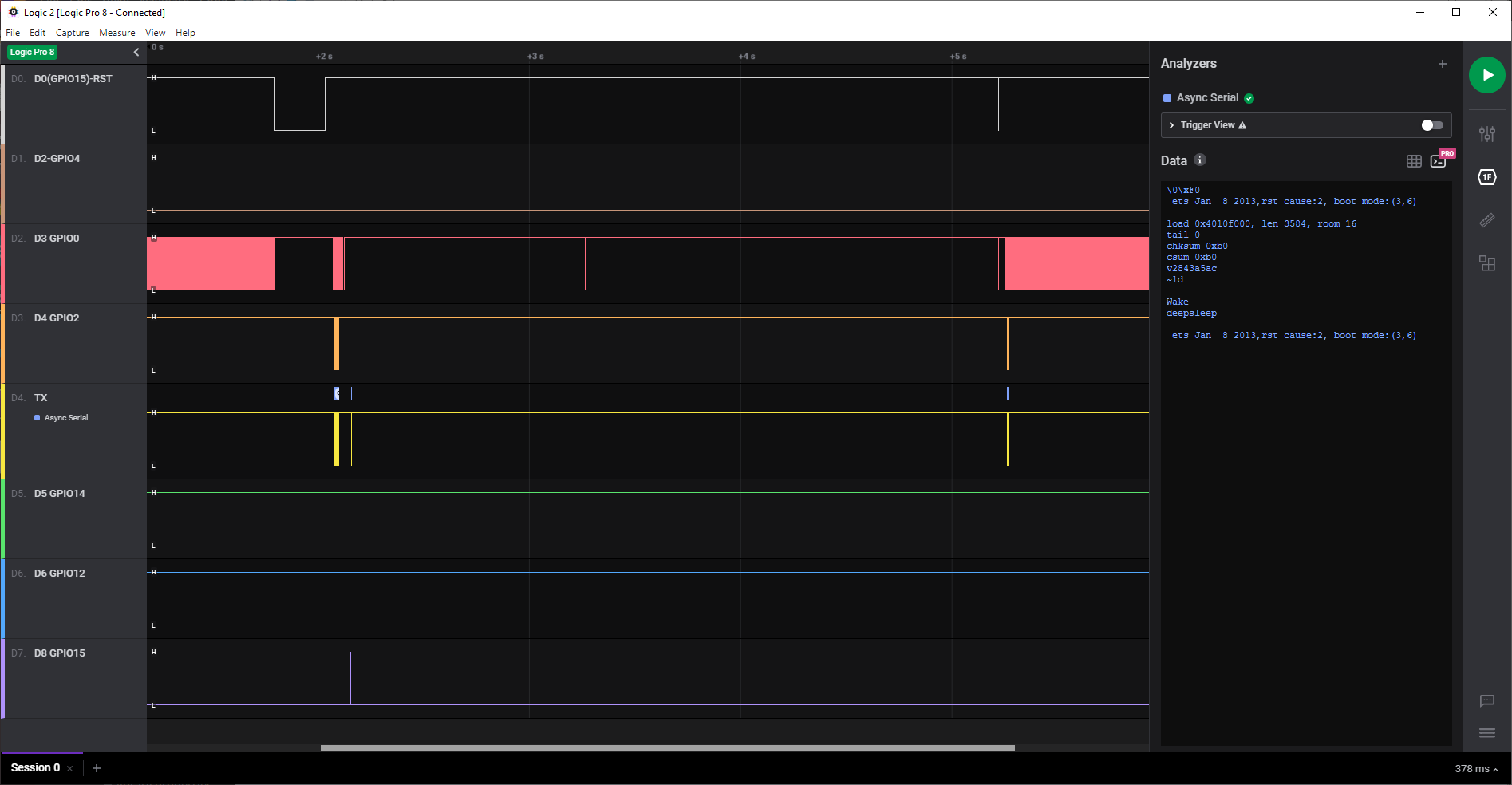
If you want to open the logic analyzer file, you can download the free tool from
https://ideas.saleae.com/f/changelog/
ESP8266WemosD1MiniDeepSleep.zip
What I see is a constant clock on GPIO0 (D3). Is that normal?
Erriez
on 13 Oct 2020
I'm probably as old as your dad or older: I remember dinosaurs. :D
If you see a clock on GPIO0 then it's likely stuck in test mode. It thinks it saw a LOW on TXD0 during boot. You're the first person mentioning that GPIO0 is toggling.
What I meant about the esptool test was while it was in 'zombie mode'. If it's stuck in 'flash programming' mode then esptool should be able to query the flash. If it's normally come out of Deep Sleep or it's doing something else weird then esptool can't communicate with it, only in flash mode. However, with GPIO0 toggling, it's not in flash mode.
You ran the chip_id, I was hoping for flash_id to see which manufacturer of flash. However, with the RF shield removed, you can read it directly. What's on the flash chip? (just curious, in case it matters)
I got my D1 Mini boards from here. 2 to 3 times what you paid, but mine all work. ;-) I think that alice1101983 or DIYMore also sell these. Looks like the price went up since I bought them. I paid ~ 3.25USD last year.
Here's the actual mode selection table:
| TXD0-GPIO1 | MTDO-GPIO15 | GPIO0 | TXD1-GPIO2 | Mode |
|:----:|:----:|:-----:|:-----:|---------------|
| 1 | 1 | X | X | SDIO/SPI WiFi |
| 1 | 0 | 0 | 1 | UART Download |
| 1 | 0 | 1 | 1 | Flash Boot |
| 0 | X | X | X | Chip Test |
Tech-TX
on 14 Oct 2020
@Erriez
Hi,
1) testnk without SDK works fine, but testNK with SDK only once? Right?
2) What is the voltage level on GPIO0 when testNK with SDK doesn't Wake up ?
3) If possible, check the operation of the tests not on Wemos, but on ESP-12. Or disable the control scheme on Wemos.
nikolz0
on 14 Oct 2020
@Tech-TX @nikolz0, First I have to say thank you for your support so far. It is an interesting investigation and I appreciate your help.
If you see a clock on GPIO0 then it's likely stuck in test mode.
I see this for the first time, but it looks like normal:
https://bbs.espressif.com/viewtopic.php?t=1485
GPIO0 outputs the clock frequency of the external cystal(e.g. 26MHz) by default, which cannot be modified.
Even you can modify the functions of GPIO0 in the codes, however, before programm starts to run, GPIO0 still outputs the clock frequency of the external cystal.
The clock on GPIO0 is around 1MHz.
It thinks it saw a LOW on TXD0 during boot.
I've added a 1k pull-up to TXD, but does not help.
You're the first person mentioning that GPIO0 is toggling.
I don't think so when I search on internet. :-) I did not notice this before.
However, with GPIO0 toggling, it's not in flash mode.
Confirmed:
- GPIO0 D3 low after reset:
ets Jan 8 2013,rst cause:2, boot mode:(1,6), no clock on GPIO0 (shorted) - GPIO0 D3 high after reset:
ets Jan 8 2013,rst cause:2, boot mode:(3,6), 1MHz clock on GPIO0
What I meant about the esptool test was while it was in 'zombie mode'. If it's stuck in 'flash programming' mode then esptool should be able to query the flash.
The esptool does not respond when RST and GPIO16 are connected together. Disconnecting displays:
$ ./esptool.py -p /dev/ttyUSB0 flash_id
esptool.py v2.8
Serial port /dev/ttyUSB0
Connecting....
Detecting chip type... ESP8266
Chip is ESP8266EX
Features: WiFi
Crystal is 26MHz
MAC: c8:2b:96:2f:8e:c6
Uploading stub...
Running stub...
Stub running...
Manufacturer: 0b
Device: 4016
Detected flash size: 4MB
Hard resetting via RTS pin...
Manufacturer 0b does not sound good. From the same seller I received in the same batch another ESP8266EX D1 Pro Mini DOA which also contains damaged 16MB flash with chip type: 25Q12BFVG 1634.
What's on the flash chip? (just curious, in case it matters)
XT26F32B 1824X9GB:
- Company:
XTX - Product family:
25F =2.7~3.6V Serial Flash Memory - Product density:
32B = 32M bit
I got my D1 Mini boards from here.
Oh I did not expect E-Bay. I always thought that they deliver the same low quality as Aliexpress. You're lucky that they work, but you never know what's delivered tomorrow...
Today I've no other ideas.
- testnk without SDK works fine, but testNK with SDK only once? Right?
Yes, your first sketch is the only one which wakes correctly after deepsleep. The others with SDK does not wake.
- What is the voltage level on GPIO0 when testNK with SDK doesn't Wake up?
Flash tool settings (for my reference):
Does not wake, measured on the RST pin (see Vmax1 = 3.751V and Vmin1 is a spike -439mV):
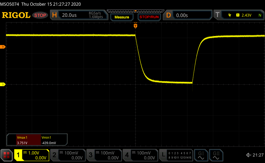
- If possible, check the operation of the tests not on Wemos, but on ESP-12. Or disable the control scheme on Wemos.
Working ESP8266 bare board on RST pin, a much better reset pulse (see Vmax1 = 3.761V and Vmin1= 39mV):

Note: The broken Wemos contains an internal 5k6 pull-up resistor on the RST pin and the IA Tinker schematic shows 12k.
Do you recommend me to replace this incorrect resistor?
I can also measure directly on the flash chip with my logic analyzer if you want.
Erriez
on 14 Oct 2020
testnk without SDK works fine, but testNK with SDK only once? Right?
Yes, your first sketch is the only one which wakes correctly after deepsleep. The others with SDK does not wake.
That means something in the SDK (boot or hand-over) is going awry.
re: the clock on GPIO0, I misunderstood. The output on GPIO0 is normal, but it's brief. I'd thought you said it was doing it continuously. You don't want to short GPIO0 permanently low or high, a 10-12K pull-up and grounded until after RST for programming / flash upload.
I don't know anything about the XTX chips, but if they run code without the Deep Sleep it's less likely to be that. This is more about the reset detection, I think. Connecting a wire from GPIO16 > RST should have cured that, so we're still on the hunt.
I doubt the 5.6K pullup on RST will cause problems, but it will make the rising time shorter. Can you see what value pullup they have on the CH_PD pin? You can measure it with an ohmmeter to 3.3V (easiest). I saw something in one of the databooks on RST / CH_PD sequencing which could conceivably cause your problem, although I'd expect a boot message with 'ets_main.c' in that case.
Those soft edges on the RST pulse with your D1 Mini are due to a capacitor to GND on the RST line. That's usually both OK and preferred, as it reduces noise on RST. A bare -12F module doesn't have the ~ .1uF to 1uF cap. I'm not sure if the ESP-12S has the cap, although it has pullups / pulldowns, same as the other 'S' version modules.
WinBond W25Q128FV is probably the most reliable Flash chip, but I'm not at all surprised if someone re-labeled a cheap flash with that number. WinBond will have a Manufacturer ID of 0xEF, but if it's dead you can't read the ID (maybe, maybe not).
Tech-TX
on 15 Oct 2020
@Erriez
Hi,
Here is a testnk with the SDK and with my deepsleep function.
testnkf_SDK.zip
I propose to conduct the following experiment.
Upload the testnk c SDK to Wemos.
Check the operation of Wemos and the state of GPIO16.
Then remove the two s8050 transistors from the Board.
After that, wemos will always be in working mode.
You can set button GPIO0 to control the Wemos mode.
Check the operation of Wemos and the state of GPIO16.
nikolz0
on 15 Oct 2020
@Tech-TX
Can you see what value pullup they have on the CH_PD pin?
Yes, there is a 10k on the WeMos PCB between the ESP8266 PCB and 3V3, so that looks good.
WinBond W25Q128FV is probably the most reliable Flash chip, but I'm not at all surprised if someone re-labeled a cheap flash with that number.
This chip is a good candidate for chip pirates...
WinBond will have a Manufacturer ID of 0xEF, but if it's dead you can't read the ID (maybe, maybe not).
The esptool cannot read the chip ID on that Pro mini board, so I'm sure that there is a chip or PCB problem. I bought it for 16MB flash instead of 4MB to store sensor samples when WiFi is not available. I consider to remove that chip and wire it to an UNO to check if this chip is alive or not. But that's for later.
Let's check Nikolz0 output which is interesting...
Erriez
on 15 Oct 2020
@nikolz0
Here is a testnk with the SDK and with my deepsleep function.
Ok, I've flashed testnkf_SDK.zip from https://github.com/esp8266/Arduino/issues/6318#issuecomment-708884215
I propose to conduct the following experiment.
Upload the testnk c SDK to Wemos.
Check the operation of Wemos and the state of GPIO16.
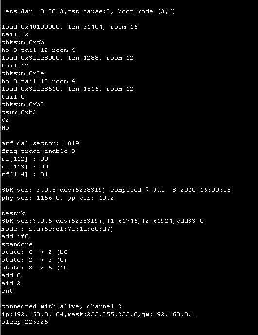
The output with a wire between RST and D0:
20:51:26.378 ->
20:51:26.378 ->  ets Jan  8 2013,rst cause:2, boot mode:(3,6)
20:51:26.378 ->
20:51:26.444 -> load 0x40100000, len 31404, room 16
20:51:26.478 -> tail 12
20:51:26.478 -> chksum 0xcb
20:51:26.478 -> ho 0 tail 12 room 4
20:51:26.478 -> load 0x3ffe8000, len 1288, room 12
20:51:26.478 -> tail 12
20:51:26.478 -> chksum 0x2e
20:51:26.478 -> ho 0 tail 12 room 4
20:51:26.478 -> load 0x3ffe8510, len 1516, room 12
20:51:26.511 -> tail 0
20:51:26.511 -> chksum 0xb2
20:51:26.511 -> csum 0xb2
20:51:26.511 -> V2
20:51:26.511 -> Mo
20:51:26.511 -> ⸮rf cal sector: 1019
20:51:26.511 -> freq trace enable 0
20:51:26.511 -> rf[112] : 00
20:51:26.511 -> rf[113] : 00
20:51:26.544 -> rf[114] : 01
20:51:26.544 ->
20:51:26.544 -> SDK ver: 3.0.5-dev(52383f9) compiled @ Jul  8 2020 16:00:05
20:51:26.544 -> phy ver: 1156_0, pp ver: 10.2
20:51:26.544 ->
20:51:26.544 -> testnk
20:51:26.544 -> SDK ver:3.0.5-dev(52383f9),T1=92096,T2=92392,vdd33=0
20:51:26.544 -> mode : sta(c8:2b:96:2f:8e:c6)
20:51:26.544 -> add if0
20:51:29.372 -> scandone
20:51:29.372 -> no alive found, reconnect after 1s
20:51:29.472 -> reconnect
20:51:30.738 -> sleep=4312955
20:51:39.893 ->
20:51:39.893 ->  ets Jan  8 2013,rst cause:2, boot mode:(3,6)
20:51:39.893 ->
20:51:39.960 -> load 0x40100000, len 31404, room 16
20:51:39.993 -> tail 12
20:51:39.993 -> chksum 0xcb
20:51:39.993 -> ho 0 tail 12 room 4
20:51:39.993 -> load 0x3ffe8000, len 1288, room 12
20:51:39.993 -> tail 12
20:51:39.993 -> chksum 0x2e
20:51:39.993 -> ho 0 tail 12 room 4
20:51:39.993 -> load 0x3ffe8510, len 1516, room 12
20:51:40.026 -> tail 0
20:51:40.026 -> chksum 0xb2
20:51:40.026 -> csum 0xb2
20:51:40.026 -> V2
20:51:40.026 -> Mo
20:51:40.026 -> ⸮rf cal sector: 1019
20:51:40.026 -> freq trace enable 0
20:51:40.026 -> rf[112] : 00
20:51:40.026 -> rf[113] : 00
20:51:40.059 -> rf[114] : 01
20:51:40.059 ->
20:51:40.059 -> SDK ver: 3.0.5-dev(52383f9) compiled @ Jul  8 2020 16:00:05
20:51:40.059 -> phy ver: 1156_0, pp ver: 10.2
20:51:40.059 ->
20:51:40.059 -> testnk
20:51:40.059 -> SDK ver:3.0.5-dev(52383f9),T1=92044,T2=92339,vdd33=0
20:51:40.059 -> mode : sta(c8:2b:96:2f:8e:c6)
20:51:40.059 -> add if0
20:51:42.886 -> scandone
20:51:42.886 -> no alive found, reconnect after 1s
20:51:42.985 -> reconnect
20:51:44.249 -> sleep=4312903
20:51:53.398 ->
20:51:53.398 ->  ets Jan  8 2013,rst cause:2, boot mode:(3,6)
20:51:53.398 ->
20:51:53.465 -> load 0x40100000, len 31404, room 16
20:51:53.499 -> tail 12
20:51:53.499 -> chksum 0xcb
20:51:53.499 -> ho 0 tail 12 room 4
20:51:53.499 -> load 0x3ffe8000, len 1288, room 12
20:51:53.499 -> tail 12
20:51:53.499 -> chksum 0x2e
20:51:53.499 -> ho 0 tail 12 room 4
20:51:53.499 -> load 0x3ffe8510, len 1516, room 12
20:51:53.532 -> tail 0
20:51:53.532 -> chksum 0xb2
20:51:53.532 -> csum 0xb2
20:51:53.532 -> V2
20:51:53.532 -> Mo
20:51:53.532 -> ⸮rf cal sector: 1019
20:51:53.532 -> freq trace enable 0
20:51:53.532 -> rf[112] : 00
20:51:53.532 -> rf[113] : 00
20:51:53.565 -> rf[114] : 01
20:51:53.565 ->
20:51:53.565 -> SDK ver: 3.0.5-dev(52383f9) compiled @ Jul  8 2020 16:00:05
20:51:53.565 -> phy ver: 1156_0, pp ver: 10.2
20:51:53.565 ->
20:51:53.565 -> testnk
20:51:53.565 -> SDK ver:3.0.5-dev(52383f9),T1=92099,T2=92395,vdd33=0
20:51:53.565 -> mode : sta(c8:2b:96:2f:8e:c6)
20:51:53.565 -> add if0
20:51:56.395 -> scandone
20:51:56.395 -> no alive found, reconnect after 1s
20:51:56.495 -> reconnect
20:51:57.762 -> sleep=4312958
...
Then remove the two s8050 transistors from the Board.
I decided to keep the transistors, because this sketch boots. Do you still want me to remove them?
I've flashed testnk_SDK_Wifi_off.zip as well from https://github.com/esp8266/Arduino/issues/6318#issuecomment-709420065
But unfortunately, this one does not wake with the same wire between RST and D0:
20:46:55.988 ->  ets Jan  8 2013,rst cause:2, boot mode:(3,6)
20:46:55.988 ->
20:46:56.088 -> load 0x40100000, len 31400, room 16
20:46:56.121 -> tail 8
20:46:56.121 -> chksum 0xeb
20:46:56.121 -> load 0x3ffe8000, len 1288, room 0
20:46:56.121 -> tail 8
20:46:56.121 -> chksum 0x06
20:46:56.121 -> load 0x3ffe8510, len 1516, room 0
20:46:56.121 -> tail 12
20:46:56.121 -> chksum 0x96
20:46:56.121 -> csum 0x96
20:46:56.154 -> V2
20:46:56.154 -> Mo
20:46:56.188 -> ⸮rf cal sector: 1019
20:46:56.188 -> freq trace enable 0
20:46:56.188 -> rf[112] : 00
20:46:56.188 -> rf[113] : 00
20:46:56.188 -> rf[114] : 01
20:46:56.188 ->
20:46:56.188 -> SDK ver: 3.0.5-dev(52383f9) compiled @ Jul  8 2020 16:00:05
20:46:56.221 -> phy ver: 1156_0, pp ver: 10.2
20:46:56.221 ->
20:46:56.221 -> testnk
20:46:56.221 -> enter deep sleep
Notes:
- I've flashed both sketches twice after each other to double check that I don't make any mistakes here. Both with the same output.
- Same flash settings as previous binaries.
I think there is a little break trough as the first binary wakes. Is this what you expected. :+1: for this.
Erriez
on 15 Oct 2020
@nikolz0
did I understand you correctly that the tests with my function works correctly, and tests with a function from the SDK stop?
I'm not sure what you mean, but I loaded your binaries on the non-working board:
testnkf_SDK.zip https://github.com/esp8266/Arduino/issues/6318#issuecomment-708884215 -> Wake-up works as expected. I hope you have more information about the contents of this binary.
testnk_SDK_Wifi_off.zip https://github.com/esp8266/Arduino/issues/6318#issuecomment-709420065 -> Wake-up does not work.
QIO or DIO does not matter. I assume this setting is only used when writing the binaries to the flash chip. Writing to flash, booting from flash after power-on or pressing the reset button works reliable.
Erriez
on 16 Oct 2020
@nikolz0
I've created the following table:
Sketch | Date | Deep sleep | Wake |Status | Post
------- | ----- | ------ | ----- | ----- | -----
testnk.zip | 10 Oct 2020 | 132 uA | | Works! | https://github.com/esp8266/Arduino/issues/6318#issuecomment-706560461
testnk_SDK_305.zip | 12 Oct 2020 | 132uA | 35mA | Does not start sketch after wake | https://github.com/esp8266/Arduino/issues/6318#issuecomment-706845183
testnkf_SDK.zip | 15 Oct 2020 | 132uA | | Works! | https://github.com/esp8266/Arduino/issues/6318#issuecomment-708884215
testnk_SDK_Wifi_off.zip | 15 Oct 2020 | 118uA | 36mA | Does not start sketch after wake | https://github.com/esp8266/Arduino/issues/6318#issuecomment-709420065
Let me know if you need more information.
Erriez
on 16 Oct 2020
Hi,
I've extracted the libespnow.zip into ~/Arduino/hardware/esp8266com/esp8266/tools/sdk/lib/NONOSDK221/libespnow.a
In the Arduino IDE:
- Board to
Generic ESP8266 Module - Espressif FW: "nonos-sdk 2.2.2 (legacy)"
#include <ESP8266WiFi.h>

#define T1 1.32*10000000 //sleep 10 seconds

extern void DeepSleepNK(uint32 );

void setup() {
    Serial.begin(74880);
    Serial.println(F("Wake"));
    delay(1000);
    Serial.println(F("Deepsleep"));
    //ESP.deepSleep(3000000);
    DeepSleepNK(T1); //function call
}

void loop() {
}
~/Arduino/hardware/esp8266com/esp8266/tools/xtensa-lx106-elf/bin/xtensa-lx106-elf-gcc -fno-exceptions -Wl,-Map -Wl,/tmp/arduino_build_957326/sketch_oct16a.ino.map -g -Wall -Wextra -Os -nostdlib -Wl,--no-check-sections -u app_entry -u _printf_float -u _scanf_float -Wl,-static -L~/Arduino/hardware/esp8266com/esp8266/tools/sdk/lib -L~/Arduino/hardware/esp8266com/esp8266/tools/sdk/lib/NONOSDK221 -L~/Arduino/hardware/esp8266com/esp8266/tools/sdk/ld -L~/Arduino/hardware/esp8266com/esp8266/tools/sdk/libc/xtensa-lx106-elf/lib -Teagle.flash.1m64.ld -Wl,--gc-sections -Wl,-wrap,system_restart_local -Wl,-wrap,spi_flash_read -o /tmp/arduino_build_957326/sketch_oct16a.ino.elf -Wl,--start-group /tmp/arduino_build_957326/sketch/sketch_oct16a.ino.cpp.o /tmp/arduino_build_957326/libraries/ESP8266WiFi/ESP8266WiFi.a /tmp/arduino_build_957326/core/core.a -lhal -lphy -lpp -lnet80211 -llwip2-536-feat -lwpa -lcrypto -lmain -lwps -lbearssl -lespnow -lsmartconfig -lairkiss -lwpa2 -lstdc++ -lm -lc -lgcc -Wl,--end-group -L/tmp/arduino_build_957326
~/Arduino/hardware/esp8266com/esp8266/tools/xtensa-lx106-elf/bin/../lib/gcc/xtensa-lx106-elf/10.2.0/../../../../xtensa-lx106-elf/bin/ld: /tmp/arduino_build_957326/sketch/sketch_oct16a.ino.cpp.o:(.text.setup+0x14): undefined reference to `_Z11DeepSleepNKj'
~/Arduino/hardware/esp8266com/esp8266/tools/xtensa-lx106-elf/bin/../lib/gcc/xtensa-lx106-elf/10.2.0/../../../../xtensa-lx106-elf/bin/ld: /tmp/arduino_build_957326/sketch/sketch_oct16a.ino.cpp.o: in function `setup':
/tmp/arduino_modified_sketch_375601/sketch_oct16a.ino:9: undefined reference to `_Z11DeepSleepNKj'
collect2: error: ld returned 1 exit status
Where should I extract the deepsleepnk.zip?
Erriez
on 16 Oct 2020
Hi,
Find libespnow.a in the arduino folder and replace it.
There are multiple directories with libespnow.a:
$ find Arduino/hardware/esp8266com -name libespnow.a
Arduino/hardware/esp8266com/esp8266/tools/sdk/lib/NONOSDK221/libespnow.a <= Legacy (2.2.1)
Arduino/hardware/esp8266com/esp8266/tools/sdk/lib/NONOSDK22x_190313/libespnow.a
Arduino/hardware/esp8266com/esp8266/tools/sdk/lib/NONOSDK22x_190703/libespnow.a
Arduino/hardware/esp8266com/esp8266/tools/sdk/lib/NONOSDK22x_191024/libespnow.a
Arduino/hardware/esp8266com/esp8266/tools/sdk/lib/NONOSDK22x_191105/libespnow.a
Arduino/hardware/esp8266com/esp8266/tools/sdk/lib/NONOSDK22x_191122/libespnow.a <= Latest version 2
Arduino/hardware/esp8266com/esp8266/tools/sdk/lib/NONOSDK3V0/libespnow.a <= Version 3 (experimental)
https://randomnerdtutorials.com/esp-now-esp8266-nodemcu-arduino-ide/
Write a sketch to check out espnow. If there are no errors, the library is available. Then replace it with my version.
The example sketch ESP8266 NodeMCU Sender Sketch (ESP-NOW) works with the original libespnow.a.
When I replace it, for example in NONOSDK22x_191122/, it generates build errors:
/tmp/arduino_modified_sketch_393109/sketch_oct17a.ino:34: undefined reference to `esp_now_init'
~/Arduino/hardware/esp8266com/esp8266/tools/xtensa-lx106-elf/bin/../lib/gcc/xtensa-lx106-elf/10.2.0/../../../../xtensa-lx106-elf/bin/ld: /tmp/arduino_modified_sketch_393109/sketch_oct17a.ino:42: undefined reference to `esp_now_set_self_role'
~/Arduino/hardware/esp8266com/esp8266/tools/xtensa-lx106-elf/bin/../lib/gcc/xtensa-lx106-elf/10.2.0/../../../../xtensa-lx106-elf/bin/ld: /tmp/arduino_modified_sketch_393109/sketch_oct17a.ino:43: undefined reference to `esp_now_register_send_cb'
~/Arduino/hardware/esp8266com/esp8266/tools/xtensa-lx106-elf/bin/../lib/gcc/xtensa-lx106-elf/10.2.0/../../../../xtensa-lx106-elf/bin/ld: /tmp/arduino_modified_sketch_393109/sketch_oct17a.ino:49: undefined reference to `esp_now_add_peer'
~/Arduino/hardware/esp8266com/esp8266/tools/xtensa-lx106-elf/bin/../lib/gcc/xtensa-lx106-elf/10.2.0/../../../../xtensa-lx106-elf/bin/ld: /tmp/arduino_build_635029/sketch/sketch_oct17a.ino.cpp.o:(.text.loop+0x20): undefined reference to `esp_now_send'
~/Arduino/hardware/esp8266com/esp8266/tools/xtensa-lx106-elf/bin/../lib/gcc/xtensa-lx106-elf/10.2.0/../../../../xtensa-lx106-elf/bin/ld: /tmp/arduino_build_635029/sketch/sketch_oct17a.ino.cpp.o: in function `loop':
/tmp/arduino_modified_sketch_393109/sketch_oct17a.ino:60: undefined reference to `esp_now_send'
collect2: error: ld returned 1 exit status
Instead, you can add deepsleepnk.o to any lib... library or include this file in the build.
I'm not sure how to do this in the Arduino IDE which is probably too simple.
Which SDK version did you use?
Protocol allows you to make a network without a router and significantly reduce ESP consumption.
This is a great feature. I was not aware that it exists. I can't read it (Russian?) but Google translate is my friend.
Erriez
on 17 Oct 2020
Hi,
Post your version of libespnow.a
I choose the latest v2.2.1+119 instead of legacy:
~/Arduino/hardware/esp8266com/esp8266/tools/sdk/lib/NONOSDK22x_191122$ cat version
v2.2.1-119-ga0b1311 (shows as SDK:2.2.2-dev(a58da79) in debug mode)

~/Arduino/hardware/esp8266com/esp8266/tools/sdk/lib/NONOSDK22x_191122$ sha1sum libespnow.a
c02f152901b0206199ec6b90254c9305b832d7cc  libespnow.a   <= Original library build success

~/Arduino/hardware/esp8266com/esp8266/tools/sdk/lib/NONOSDK22x_191122$ sha1sum libespnow.a
97b8b75fbbbee1a8d81ed5bc4f555eaa4e1e51e6  libespnow.a   <= Your version: `undefined reference to esp_now_init'`
@nikolz0
#include "c_types.h"

uint32_t* RT= (uint32_t *)0x60000700;

void ICACHE_FLASH_ATTR DeepSleepNK(uint32 t_us)
{
    *RT =0x30;
    *(RT+1)=t_us>>3;
    *(RT+3) = 0x640C8;
    *(RT+4) = 0;
    *(RT+6) = 0x18;
    *(RT+17) = 4;
    *(RT+39) = 0x11;
    *(RT+40) = 0x03;
    *(RT+2) |= 1<<20;
    __asm volatile ("waiti 0");
}

void setup() {
    #define Time_us 10000000
    #define Time 1.31*Time_us
    DeepSleepNK(Time);
}

void loop() {
}
This sketch boots every ~10 seconds, but the power consumption is 5.85mA. Do you know why?
Erriez
on 18 Oct 2020
@nikolz0
#include "c_types.h"
#include <user_interface.h>


uint32_t* RT= (uint32_t *)0x60000700;

void DeepSleepNK(uint32 t_us)
{
    *RT =0x30;
    //PIN_FUNC_SELECT(PERIPHS_IO_MUX_U0TXD_U,3);
    //gpio_output_set(2, 0,2, 0);
    system_deep_sleep_instant(t_us);
}

void setup() {
    #define Time_us 10000000
    DeepSleepNK(Time_us);
}

void loop() {
}
Problem is back: This sketch does not start the sketch after wake.
Erriez
on 18 Oct 2020
@nikolz0
Now we're back to the original reported problem from my first post in this thread:
The sketch https://github.com/esp8266/Arduino/issues/6318#issuecomment-711311429 does not start the sketch after wake..
Note: I use the reverted the SDK libraries to NONOSDK22x_191122.
Erriez
on 18 Oct 2020
@Erriez
include "c_types.h"
uint32_t*RT= (uint32_t *)0x60000700;
void DeepSleepNK(uint32 t_us)
{
RT[4] = 0;
*RT = 0;
RT[1]=100;
RT[3] = 0x10010;
RT[6] = 8;
RT[17] = 4;
RT[2] = 1<<20;
ets_delay_us(10);
RT[1]=t_us>>3;
RT[3] = 0x640C8;
RT[4]= 0;
RT[6] = 0x18;
RT[16] = 0x7F;
RT[17] = 0x20;
RT[39] = 0x11;
RT[40] = 0x03;
RT[2] |= 1<<20;
__asm volatile ("waiti 0");
}
nikolz0
on 18 Oct 2020
@nikolz0 @Tech-TX
#include "c_types.h"

uint32_t*RT= (uint32_t *)0x60000700;

void DeepSleepNK(uint32 t_us)
{
    RT[4] = 0;
    *RT = 0;
    RT[1]=100;
    RT[3] = 0x10010;
    RT[6] = 8;
    RT[17] = 4;
    RT[2] = 1<<20;
    ets_delay_us(10);
    RT[1]=t_us>>3;
    RT[3] = 0x640C8;
    RT[4]= 0;
    RT[6] = 0x18;
    RT[16] = 0x7F;
    RT[17] = 0x20;
    RT[39] = 0x11;
    RT[40] = 0x03;
    RT[2] |= 1<<20;
    __asm volatile ("waiti 0");
}


void setup() {
    // put your setup code here, to run once:
    #define Time_us 10000000
    #define Time 1.31*Time_us
    DeepSleepNK(Time);
}

void loop() {
}
Yes this sketch works! It wakes every ~10 seconds and the current is 132uA in deep sleep. I don't understand why the Espressif SDK does not work and this sketch works as expected.
Erriez
on 18 Oct 2020
Yes, that piece works on 2 of my units as well. However, it's a pointless exercise as all it's doing is bypassing the Arduino wrapper and SDK calls for Deep Sleep, and I sincerely doubt @devyte is eager to trade one undocumented binary blob for another. At a minimum we need to know how to do:
Deep Sleep, wake with default modem settings
Deep Sleep, wake with RFCAL
Deep Sleep Instant, wake with NO_RFCAL
Deep Sleep Instant, wake with RF_DISABLED
(I've probably missed several there, basically all of the different modes with/without that first RT[4] = 0; as that's doing the equivalent of Deep Sleep Instant.
From what I can tell, nikolz0' code is doing "_Deep Sleep Instant, wake with default modem settings_", as I saw what looked like an RF CAL happen occasionally,
I added a 2 second delay before the sleep code kicked in so I could measure the current. Without that delay it's:
By the way, I'm getting the same 16uA substrate current during Deep Sleep when I run that on my gutted board.
Tech-TX
on 19 Oct 2020
Hmmm. Re-reading the thread so far, I just noticed that I haven't asked where you're powering the D1 Mini from, @Erriez
Looking at other threads, nobody else has mentioned a 5.6K pull-up on RST, so I'd change that to 12K as a test if you can. That ESP-12F board may have gotten a wrong part. No way to tell what the RST capacitor is without a cap checker as most caps aren't marked, and you can't check it in-circuit most likely.
One other thing to try: tell the IDE that you have a generic ESP8266 module and slow the flash speed down. If that flash part comes out of sleep in power-saving mode (reduced IO drive current) that could potentially cause similar problems to the XMC flash problem. I'd try slower flash clock and both DIO and DOUT, as we've seen one flash part sensitive to DOUT.
Tech-TX
on 19 Oct 2020
@Erriez ,
Hi,
add these commands to reduce the current and active time.
It is more correct to write like this:
define Time_us 10000000 //time deepsleep
define Time 1.31*Time_us
void setup() {
system_phy_set_powerup_option(2); // calibrate only 2ms;
system_deep_sleep_set_option(2); //deepsleep
}
void loop() {
// user code
...
//deep_sleep
SET_PERI_REG_MASK(UART_CONF0(0), UART_TXFIFO_RST); //RESET FIFO
CLEAR_PERI_REG_MASK(UART_CONF0(0), UART_TXFIFO_RST);
DeepSleepNK(Time);
}
nikolz0
on 19 Oct 2020
Hi,
the pull-up resistor can be set from 2.2 k to 47 k.
I use 4.7 k,10k resistors.
nikolz0
on 19 Oct 2020
@Erriez ,
a few tips:
you can slightly reduce the current of the transmitter if you reduce its power.
This is done like this:
void setup() {
system_phy_set_powerup_option(2); // calibrate only 2ms;
system_deep_sleep_set_option(2); //deepsleep
system_phy_set_max_tpw(82); //0-82 , 1=0.25dB
}
To reduce the current consumption when exchanging data within a local network, it is better to use the UDP or ESP-NOW Protocol.
To reduce the current from the battery or solar panel when the transmitter is running, I use a 1f super capacitor.
One charge of the capacitor is enough for the ESP8266(ESP8285) to Wake up and transmit data 20 times.
This is how I make sensors that can only work from a solar panel of 8x6 cm2.
In addition, I use the validation of the sensors inside of the bootloader.
If the data is not transmitted, the ESP8266(ESP8285) goes to sleep. In this mode, the current consumption is 12 mA instead of 70ma.
The minimum operating time is less than 0.1 seconds.
As a result, energy consumption is reduced by 10 or more times compared to the standard solution.
Read my article, "How to reduce the consumption of wifi modules by ten or more times"
https://habr.com/ru/post/480316/
where I briefly described the options for reducing the energy consumption of ESP8266(ESP8285).
nikolz0
on 19 Oct 2020
Hi @Tech-TX,
However, it's a pointless exercise as all it's doing is bypassing the Arduino wrapper and SDK calls for Deep Sleep,
I agree. Adding another function is not portable between devices.
After all investigations, only one of the sketches from nikolz0 works https://github.com/esp8266/Arduino/issues/6318#issuecomment-711389479, I still have no idea about the root cause:
- Is it related to the WeMos PCB? Probably not.
- Is it related to the ESP8266 PCB? The RST pull-up is 5k6 instead of 10k, but as @nikolz0 mentioned within range.
- Is the on-chip ROM different? On https://github.com/esp8266/esp8266-wiki/wiki/Memory-Map I found internal ROM at 40000000h: _May be writable somehow, but details unknown._ I'm not sure if this can be verified or if there is other firmware inside the chip which may be different.
- Is this problem related to the ESP8266EX chip itself?
I just noticed that I haven't asked where you're powering the D1 Mini from
I started with USB only, but to measure the current, I connect a 3.3V external power supply to the 3V3 pin. I use a Fluke 87 to measure current. 132uA in deep sleep WeMos D1 mini is one of the best I have in my collection. Otherwise it is required to remove the voltage regulator, a diode and regulator or by cutting a wire on the PCB. The problem is that there are different PCB's.
tell the IDE that you have a generic ESP8266 module and slow the flash speed down.
I already tried all combinations (80MHz / 20MHz, DOUT / DIO, VTable in flash / iRAM, Exceptions enabled, different SDK versions), but none of them works. Reading/writing flash works reliable.
#include <ESP8266WiFi.h>
#include "uart_register.h"

#define Time_us 10000000 //time deepsleep
#define Time 1.31*Time_us

uint32_t* RT= (uint32_t *)0x60000700;

void ICACHE_FLASH_ATTR DeepSleepNK(uint32 t_us)
{
    *RT =0x30;
    *(RT+1)=t_us>>3;
    *(RT+3) = 0x640C8;
    *(RT+4) = 0;
    *(RT+6) = 0x18;
    *(RT+17) = 4;
    *(RT+39) = 0x11;
    *(RT+40) = 0x03;
    *(RT+2) |= 1<<20;
    __asm volatile ("waiti 0");
}

void setup() {
    system_phy_set_powerup_option(2); // calibrate only 2ms;
    system_deep_sleep_set_option(2); //deepsleep

    // deep_sleep
    SET_PERI_REG_MASK(UART_CONF0(0), UART_TXFIFO_RST); //RESET FIFO
    CLEAR_PERI_REG_MASK(UART_CONF0(0), UART_TXFIFO_RST);
    DeepSleepNK(Time);
}

void loop() {
}
Sketch above wakes every 10 seconds, but the current in deep sleep is also 5.8mA, identical to https://github.com/esp8266/Arduino/issues/6318#issuecomment-711174173.
you can slightly reduce the current of the transmitter if you reduce its power.
This is done like this:
void setup() {
    system_phy_set_powerup_option(2); // calibrate only 2ms;
    system_deep_sleep_set_option(2); //deepsleep
    system_phy_set_max_tpw(82); //0-82 , 1=0.25dB
}
Good to know this, because the first call is not used in this repository.
I'm wondering that you have a ESP8266 operational on a solar panel. I never had success with it, because the slowly rising voltage results in at least 50mA at 1.7V. A reset is only generated at 1.8V an higher. Which board are you using? Do you have a special reset circuit? Now I generate the reset externally with an ATMega328 at slow clock.
If the data is not transmitted, the ESP8266(ESP8285) goes to sleep. In this mode, the current consumption is 12 mA instead of 70ma.
void setup() {
    delay(5000);
    ESP.deepSleep(2000000, RF_DISABLED);
}
On my best ESP8266 bare board I measure 14.2mA after the wake.
Erriez
on 19 Oct 2020
I have zero problem replacing one blob with another provided that:
- the new blob solves a problem for all cases
- the new blob does not introduce a new problem in any case whatsoever
In addition, the code above that works isn't exactly a blob, but rather weird undocumented register ops compiled on our side. As such, it would be under our control, i. e. modifiable in the future, which is a step better than what we have now: a precompiled closed blob in a .a archive that we can't really touch.
I suggest proceeding as follows (@Tech-TX will find this familiar :p ):
- define a code test suite that covers deep sleep in as wide a range of cases as we know, with the current code base
- implement the same tests above with the new proposed code
- test both the above on a wide range of boards, especially those known to be troublesome for deepsleep
If the above shows a strict improvement over our current sdk call use, then we can replace the internals of the EspClass method with the new code.
The above test suite would also serve for future reference in case new boards with deep sleep problems show up. Comments as to what each line does would be welcome!
devyte
on 19 Oct 2020
you can slightly reduce the current of the transmitter if you reduce its power.
This is done like this:void setup() { system_phy_set_powerup_option(2); // calibrate only 2ms; system_deep_sleep_set_option(2); //deepsleep system_phy_set_max_tpw(82); //0-82 , 1=0.25dB }Good to know this, because the first call is not used in this repository.
It _is_ used in the current repo, sorta. The default value is 0, so we're allowing the users to set it however they wish.
0: RF initialization when powerup depends on byte 114 of
esp_init_data_default.bin (0 ~ 127 bytes). For more details please see
ESP8266 SDK Getting Started Guide.
That's from page 16 of the current Non-OS API Reference v3.0.2
My best guess is the flash, since I've never heard of XTX before now. The only reference I can find googling around is in the other thread on Deep Sleep here, where the person removed the XTX and installed Winbond flash and his Deep Sleep problems disappeared. The flash recommended by Espressif 'Low Power Solutions' section 4.5.5 is ISSI IS25LQ040B. It's not quite twice the price of the equivalent Winbond, probably 4X the cost of the XTX and other bargain-bin chips.
Tech-TX
on 20 Oct 2020
I want to give it a try to order a genuine supported flash chip as you suggested and replace the XTX. Yes, the price is N times higher in a local store with shipping cost, but I've multiple devices which do not work, so it is an interesting experiment to repair them. I found the IS25LQ040B-JNLE FLASH MEMORY, 4MBIT, 104MHZ, SOIC-8 INTEGRATED SILICON SOLUTION (ISSI) in my local store.
Erriez
on 20 Oct 2020
@Erriez beware bit vs byte. From your link above:
Flash Memory Configuration : 512K x 8bit
that looks like a 512KB flash size instead of a 4MB size.
devyte
on 20 Oct 2020
@devyte Thanks! You're right, it should be a 4MByte = 32Mbit flash chip. I found IS25LP032D-JBLE NOR FLASH MEMORY 32MBIT, 133MHZ, SOIC-8 as alternative. I'd like to replace the WeMos D1 Pro Mini with 16MByte Winbond W25Q128FV flash as well, but could not find a replacement.
Erriez
on 20 Oct 2020
I just received some clone D1 Mini Pro boards I'd ordered last month. Flash reports itself as Winbond 16MB (manufacturer_ID 0xEF), although the package marking doesn't match anything I've ever seen from Winbond, and it doesn't have their name/logo on it. The only google hits I get are in Chinese... a bad sign of a no-name cloned part.
The flash seems to work OK in QIO mode, which is promising.
I found a little on XTX - they used to be Paragon, https://www.linkedin.com/company/paragon-technology-shenzhen-limited
When I run a 300 ohm resistor between GPIO16 and RST on the D1 Mini Pro and run Deep Sleep, the boot hangs at 'ets_main.c' after getting reset cause: 5 which isn't defined here in the Reset Causes... pdf. It works as expected if I use a wire or a diode in place of the resistor. I saw that 'ets_main.c' message when I tried waking from Deep Sleep using CH_PD.
edit Interesting. If I unplug the module so it loses comms with the monitor, then the current during Deep Sleep drops to around 600uA. Looks like the CP2104 on this board SUSPENDS at 100uA if it doesn't have active USB comms, and the other 500uA is probably the cheap no-name LDO. The CP2104 should also SUSPEND if I put the laptop to sleep.
Still no 'zombie mode' with the D1 Mini Pro and 13th week 2020 datecode ESP8266.
Edit part deux: Zombie mode? With the laptop asleep, a couple of times the sleep current went to 46mA and the chip never woke up: I had to hit RESET to get it awake again. I slept it 40 to 50 times when the laptop was powered, and it's erratically going off in the weeds with the laptop powered down. I suspect that's what nikolz0 was saying about the programming/reset circuit interfering. I just checked it and yes, the current when it's waiting for a download is 46mA.
Tech-TX
on 31 Oct 2020
Hi Guys,
I have the same problem with a bare ESP-12F-Module (from Amazon). I first suspected that the resetpulse to be to weak so I tryed to remove the shield and connected directly to the Resetpin of the Controller, nothing changed.
So I supeceted the pulse was to short to cause a propper reset so I tryed to enlagerge the Pulse with a Diode between GPIO16 and RST, a Cap to GND and a lager Pullup, the pulse time increased but the problem remaind. After that was searching for a solution an found this thread. I found (as you sugested) that the GPIO0 is oszilaiting after a failed deep sleep. I'm currently working on a project for my University
I'm a little bit confused with whats going on, so I don't know if I can contribute to the problem. I'm currently working on a project for my University, so I have a lot of measuring and soldering equipment on hand.
I'm supecting this problem only acures with clones or can someone provide evidence that this is a problem with a new batch of the ESP8266EX µC ?
 lmai95
on 10 Nov 2020
lmai95
on 10 Nov 2020
Hi Tech-TX,
Sorry, I missed your comment. So your cloned device with a real Winbond 16MB chip works? Hmm, that could be still my problem. However, during the replacement of the flash chip, I damaged the PCB accidentally, so I cannot continue with the investigation. )-; Ordering new cloned mini's takes weeks/months now.
With the laptop asleep, a couple of times the sleep current went to 46mA and the chip never woke up: I had to hit RESET to get it awake again.
This is interesting. I've a low-power BME280 manufactured on a 18650 battery and protection circuit which worked for around 3 weeks unattended uploading the data via MQTT every minute. It stopped uploading data unexpectedly and... Also 42mA constant current without a wake! After pressing the reset button everything works as expected. Identical behavior what you reported, but not reliable.
In the mean time I've manufactured a ATMega328 with 433MHz transmitter to send BME280 data every minute. This wake works reliable so far with 50uA in total (deep sleep MCU, transmitter and BME280) and 20mA for 50ms during transmit. That's a giant power reduction...
Additionally, the ESP8266 pins cannot wake on pin change which I need to upload high/low pin changes. Now I consider to use the same ATMega328 setup, because that's very easy to program and use.
What do you think?
Erriez
on 11 Nov 2020
Hi lmai95,
Thanks for your offer to help on this topic. There are several different (known) reset problems reported, so I'm curious which problem you encounter with your ESP8266. The reason is that there are many manufactures introducing new problems. Most of them can be solved easily, but I have a ESP8266 device (Wemos D1 mini lite clone) which does not wake with the official latest Espressif SDK (part of this thread).
Some questions:
- Which flash chip type is reported?
- What happens when connecting a wire between D0 and RST?
- What do you see on the serial port with 74400 baud by uploading the sketch below?
- Do you use the master branch of esp8266/Arduino?
// Wake every 5 seconds
void setup() {
   ESP.deepSleep(5 * 1000000);
}

void loop() {
}
Does the sketch mentioned in https://github.com/esp8266/Arduino/issues/6318#issuecomment-711389479 work for you?
I'm supecting this problem only acures with clones or can someone provide evidence that this is a problem with a new batch of the ESP8266EX µC ?
I could not find evidence that it is the ESP8266EX chip itself. In my case it looks like a counterfeit flash chip (no device ID reported), but have no evidence for that.
Thanks!
Erriez
on 11 Nov 2020
@Erriez I don't know if it will help, but I've pulled the RF shield from 3 different types of modules that all do Deep Sleep properly.
After I get done testing PWM on Saturday, I'll reverse-engineer an exact schematic of all 3. The DOIT came off of a D1 Mini, the other two are bare modules. I've done Deep Sleep OK on all 3. I'll also reverse the schematic for the salient parts of that D1 Mini, since I don't see much under the DOIT RF can. I've _seen_ schematics for all 3, but had a few people tell me they were close but not exact. I'll give you exact, except for the values of the antenna coupling cap and crystal caps. They're too low for my meter to read.
If you need to wake on a pin change, consider using the CH_PD pin instead. The chip sleeps at just a few uA when you drive CH_PD low, less current than Deep Sleep. Espressif actually recommends using CH_PD and not RST. As long as your pin change lasts long enough for the chip to boot up and do your WiFi squirt, it's an option to think about. Figure 120ms minimum for boot, plus whatever time you need to squirt WiFi. ESP-NOW is quicker at that than conventional WiFi is, but it's limited to 20 devices.
Imai95's flash chip is an XTX, so it's possibly the same flash you have.
Side note: None of the modules or boards that I know of are following the power supply sequencing specified on page 19/20 of the current ESP8266EX datasheet. Whether that matters, I can't say. Most modules I've seen have a .1uF to 1uF cap on RST, pushing it WAY after the CH_PD edge at power-up, as CH_PD usually only has a resistor.
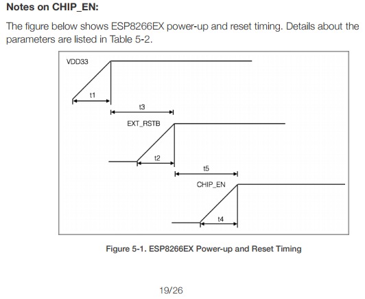
Here's what I'll be playing with probably Sunday:
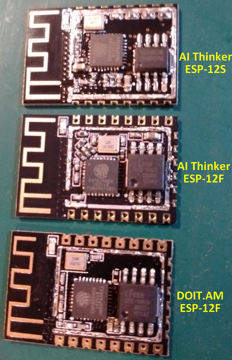
Tech-TX
on 13 Nov 2020
Say, @Erriez ? I have another clue for you. The current when you put the chip in /reset is also 46mA on this board of mine, same as what I measured when it's waiting for an upload. When you hold it in /reset as power is applied, current is 21mA.
Tech-TX
on 14 Nov 2020
@Erriez
I made a new test that checks the deep-sleep mode with and without the SDK.
Download all three files . The download address is equal to the file name.
test_ESP.zip
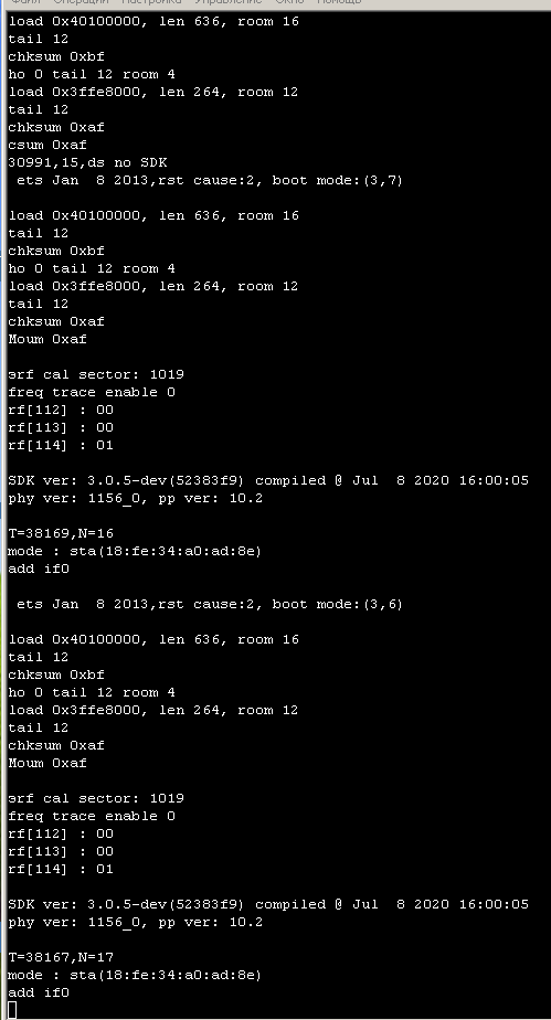
nikolz0
on 14 Nov 2020
@Tech-TX
I've pulled the RF shield from 3 different types of modules that all do Deep Sleep properly.
Interesting. I'm curious about different schematics.
When you hold it in /reset as power is applied, current is 21mA.
Yes, I measured the same.
Do you also have a version with XTX flash chip?
Do you have a version with a pull-up resistor < 10k?
To measure the capacity of the reset cap, I think I have to de-solder it.
I made a picture of my board which don't wake correctly:
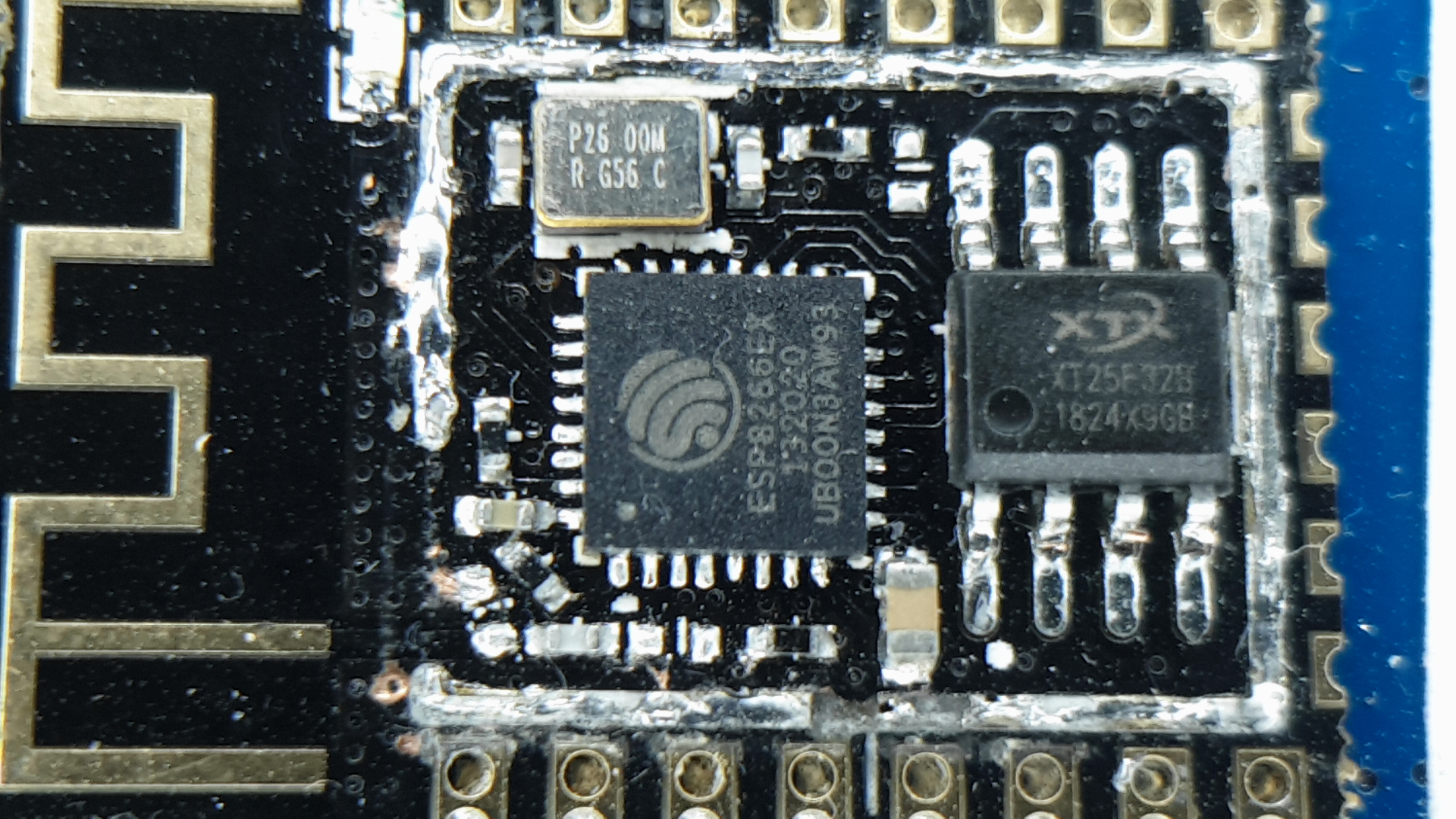
Erriez
on 14 Nov 2020
@nikolz0
I made a new test that checks the deep-sleep mode with and without the SDK.
Download all three files . The download address is equal to the file name.
Note: I've repaired the board and it is now back in the original state (without RF shield).
The wake works with a wire between RST and D0 (GPIO16)!
See the output of your ZIP file attached at 74880 baud. It is slightly different as I don't see the strings rf call sector and SDK ver:. Not sure if you expect this or not.
Erriez
on 14 Nov 2020
@Erriez
In this test I use the SDK 3.0.5.
Perhaps this is why you have an error execution -> rf_cal[0] !=0x05,is 0x00.
You can build your own test.
Write your files in the place of the second and third files.
File 0x0000.bin is a loader that either goes to sleep or loads the firmware from the second and third files.
nikolz0
on 14 Nov 2020
@nikolz0 Thanks, I'll check this.
Erriez
on 15 Nov 2020
@Erriez
The message "rf_cal[0]!=0x05, equal to 0x00 " indicates that you did not load the RF parameters in the new flash.
nikolz0
on 15 Nov 2020
@Erriez
You can make the ESP8266 current during sleep no more than 10 uA.
To do this, you need to control the ESP8266 via the CH_PD, using the TPL51xx timer,
which has a current of only 30 nA.
You can make the minimum ESP8266 activity time no more than 0.12 seconds,
if you use the ESP-NOW mode.
You can make the ESP8266 activity time for UDP data exchange no more than 0.25 seconds,
if you save the WiFi connection parameters and disable the DHCP server.
nikolz0
on 15 Nov 2020
You can make the ESP8266 activity time for UDP data exchange no more than 0.25 seconds,
if you save the WiFi connection parameters and disable the DHCP server.
Doesn't that cause writes to the flash when the ESP connects? (thus wearing out the flash at a specific address)
TD-er
on 15 Nov 2020
@TD-er
No, the parameters must be written to SRAM RTC ESP and use deep-sleep mode.
In this case, you only need to save the IP and channel, the password and name of the access point ESP saves by default.
To avoid re-recording information, you need to check whether the values saved earlier and the new ones match.
nikolz0
on 15 Nov 2020
Can you give a link to documentation for this?
Or maybe a very short piece of code to show what to write where.
Usually it takes already a few 100 msec before I can attempt to enable WiFi, so this means it has already been done before my setup() or loop() is called.
Also connecting to an AP may take upto 100 msec before the AP may reply.
So I am really curious on how you achieve such quick connection times.
TD-er
on 15 Nov 2020
@TD-er
All necessary functions are described here:
https://www.espressif.com/sites/default/files/documentation/2c-esp8266_non_os_sdk_api_reference_en.pdf
The first connection to the AP takes from 1 to 4 seconds.
When connecting, I check whether the saved username and password are equal to the current values.
After that, I write the values to the RAM RTC.
When the ESP exits sleep, the stored values are read and written to the configuration.
If the connection fails, the saved address is deleted and the connection is established again.
Be sure to disable the DHCP server, otherwise the minimum time will be 0.54 seconds instead of 0.25 seconds.
nikolz0
on 15 Nov 2020
Can you give a few commands to search for in the API reference?
TD-er
on 15 Nov 2020
@TD-er ,
as an example, here is my function for connecting to an access point:
include "ets_sys.h"
include "osapi.h"
include "user_interface.h"
include "espconn.h"
include "string.h"
include "uart.h"
include "SSID.h"
include "os_type.h"
include "stdlib.h"
include "esp8266.h"
struct station_config stationConf;
struct ip_info info;
struct {
uint32_t addr; // 4 bytes
uint8_t channel; // 1 byte, 5 in total
uint8_t bssid[6]; // 6 bytes, 11 in total The BSSID is the MAC address of the WiFi access point.
uint8_t bssid_set; // 1 byte, 12 in total
uint32_t num; // 4 byte count
} rtcData;
struct rst_info *rst_;
void ICACHE_FLASH_ATTR initUDP(){
if ( rst_->reason!=5 && rst_->reason!=6){rtcData.addr=0;
os_bzero(&rtcData,sizeof(rtcData));
}else
{ uint32 m=rtcData.addr;
if ((ip0!=ip4_addr1(&m))||(ip1!=ip4_addr2(&m))||(ip2!=ip4_addr3(&m)))rtcData.addr=0;
if (rtcData.num<0) rtcData.num=0; rtcData.num++;
}
uint8 chnl=rtcData.channel;
if(wifi_get_channel()!=chnl && chnl>0 && chnl<12 ) wifi_set_channel(chnl);
else wifi_set_channel(0);
wifi_station_get_config (&stationConf);
uint8 e1=strcmp(stationConf.ssid,_SSID);
uint8 e2=strcmp(stationConf.password,_PASSWORD);
if ((e1!=0) ||(e2!=0)){
os_bzero(&stationConf,sizeof(struct station_config));
ets_strcpy(stationConf.ssid,_SSID);
ets_strcpy(stationConf.password,_PASSWORD);
wifi_station_set_config(&stationConf);
wifi_station_set_reconnect_policy(true);
}
else if (rtcData.addr!=0 )
{ wifi_station_dhcpc_stop();
info.ip.addr=rtcData.addr;
IP4_ADDR(&info.gw, 192, 168, 0, 1);
IP4_ADDR(&info.netmask, 255, 255, 255, 0);
wifi_set_ip_info(STATION_IF, &info);
}
}
nikolz0
on 15 Nov 2020
@Erriez I have another data point for you, and a suggestion.
A person can't get a genuine Lolin NodeMCU DevKit to wake up, symptoms sounded like yours. This one doesn't use an ESP-12 module: CPU and flash are on the board itself. The photo of the board shows FT25H32S for the flash part number, which apparently is also XTX from 2018.
What I suspect is that the voltage to the flash is dropping below 3.0V during boot, and the flash can't handle it. It could be because of a thin 3.3V trace / I-R drops across a via, poor regulation from the LDO, insufficient bypass capacitor(s), or likely a combination of all three. I've taken the ESP down to ~ 2.8V and it was still running OK, so I'm less suspicious of the CPU and more suspicious of the VCC tolerance of a fly-by-night flash supplier in China that's already changed names once to protect the guilty.
I don't recall what you're using for a power supply, but if you could boost the voltage to the LDO by a couple of hundred millivolts it might be enough to overcome the VCC sag. Another way to prove it would be to run a quality 3.3V power supply right to the CPU and flash, bypassing the LDO. If it comes back from sleep when VCC isn't sagging, then there's your smoking gun. If the voltage readout on your Rigol is good enough, try monitoring VCC right at the flash during Deep Sleep wake and let us know what it's doing. VCC is pin 8, GND is pin 4.
Tech-TX
on 22 Nov 2020
When the ESP8266 comes out of sleep, the current consumption of no more than 35 mA is 10 times less than in WiFi transmission mode.
According to my research, the ESP8266 can work with a voltage of 2.6 V, and the ESP8285 from 2.2 V.
nikolz0
on 22 Nov 2020
Yes, that is why I was pointing at the flash not meeting the 2.7V specification. I've run the ESP8266 at 2.8V with a Winbond flash and had no problems.
One possible reason why your chunk of code (without the SDK) may work is that it's not doing RF_CAL when it comes out of sleep, RF_CAL is higher current than any WiFi transmission, and if there is a VCC sag it will likely occur right then.
Additionally, there's a 2ms process going on (early boot stage) before RF_PRE_INIT() that creates a lot of noise on the GPIO pins, much more noise than at any other time. It's circled in yellow below:
When the CPU doesn't load the user's code (zombie mode) has to be during that 2ms period when there is the most noise on the pins. That same noise is likely also present on the flash pins.
Tech-TX
on 22 Nov 2020
Да,именно поэтому я указывал на вспышку, не соответствующую спецификации 2,7 В. Я запустил ESP8266 на 2,8 В со вспышкой Winbond, и у меня не было никаких проблем.
Одна из возможных причин, по которой ваш кусок кода (без SDK) может работать, заключается в том, что он не делает RF_CAL, когда он выходит из спящего режима, RF_CAL имеет более высокий ток, чем любая передача Wi-Fi, и если есть провисание VCC, то это, скорее всего, произойдет именно тогда.
Кроме того, перед RF_PRE_INIT () происходит процесс 2ms (ранняя стадия загрузки), который создает много шума на выводах GPIO, гораздо больше шума, чем в любое другое время. Внизу она обведена желтым кружком:
Когда процессор не загружает код пользователя (режим зомби), он должен быть в течение этого периода 2 мс, когда на выводах больше всего шума. Этот же шум, вероятно, присутствует и на выводах вспышки.
I previously posted a test that contains three files. The first file is the loader and deep-sleep mode without the SDK.
You can easily create your own test with RF_PRE_INIT () execution and add your firmware binaries to my test instead of the second and third files.
nikolz0
on 22 Nov 2020
@nikolz0 I don't have any modules that show Deep Sleep problems - all of my modules and boards work with the standard Deep Sleep calls. All I can do from this end is suggest things that _may_ be causing trouble. From all of the different people that have described Deep Sleep trouble, the most common element is cheap flash memory on boards bought from aliexpress or eBay. My boards & modules have XMC, Eon, Winbond, and GigaDevice flash chips, and those do not have Deep Sleep problems.
edit: here's a chunk of code that I use to test Deep Sleep
#include <ESP8266WiFi.h>
#include <user_interface.h>

#define _R (uint32 *)PERIPHS_RTC_BASEADDR
#define valRTC 0xFE000000  // normal value during CONT

uint32_t rtcm = 0;

RF_PRE_INIT() {
  pinMode(4, OUTPUT);
  GPOS = (1 << 4);  // pin wiggle (1)
  String resetCause = ESP.getResetReason();
  if (resetCause == "Deep-Sleep Wake") {
    *(_R + 1) = 0x2280;
    *(_R + 3) = 0x3203C;
    *(_R + 4) = valRTC;
    *(_R + 7) = 0x3BAE;
  }
  GPOC = (1 << 4);  // pin wiggle (2)
}

void preinit() {
  pinMode(4, OUTPUT);
  GPOS = (1 << 4);  // pin wiggle (3)
  delayMicroseconds(100);
  GPOC = (1 << 4);  // pin wiggle (4)
}

void setup() {
  GPOS = (1 << 4);  // pin wiggle (5)
  delayMicroseconds(100);
  GPOC = (1 << 4);  // pin wiggle (6)
  Serial.begin(74880);
  Serial.setDebugOutput(true);
  Serial.print(F("Chip ID: esp8266-"));
  Serial.println(ESP.getChipId(), HEX);
  Serial.print(F("CPU freq: "));
  Serial.print(ESP.getCpuFreqMHz());
  Serial.println(F("MHz"));
  Serial.print(F("MAC address = "));
  Serial.println(WiFi.macAddress());
  Serial.print(F("Flash Chip ID: "));
  Serial.print(ESP.getFlashChipId(), HEX);
  Serial.println();
  Serial.print(F("Flash Chip Real Size: "));
  Serial.println(ESP.getFlashChipRealSize());
  Serial.print(F("Flash Chip IDE Size: "));
  Serial.println(ESP.getFlashChipSize());
  Serial.print(F("Flash Chip Speed: "));
  Serial.println(ESP.getFlashChipSpeed());
  Serial.print(F("Flash Chip Mode: "));
  Serial.println(ESP.getFlashChipMode());
  Serial.print(F("Core version: "));
  Serial.println(ESP.getCoreVersion());
  Serial.print(F("SDK version: "));
  Serial.println(ESP.getSdkVersion());
  Serial.print("Boot version: ");
  Serial.println(ESP.getBootVersion());
  Serial.print(F("Boot mode: "));
  Serial.println(ESP.getBootMode());
  Serial.print(F("Reset reason: "));
  Serial.println(ESP.getResetReason());
  Serial.println();

  // Connect to WiFi if we have just powered on (*not* if waking from deep sleep)
  for (int i = 0; i < 40; i++) {
    Serial.print("I = ");
    Serial.print(i);
    Serial.print(" ");
    Serial.println(*(_R + i), HEX);
  }
  String resetCause = ESP.getResetReason();
  if (resetCause == "Deep-Sleep Wake") {
    WiFi.forceSleepWake();
    String resetCause = ESP.getResetReason();
    Serial.println(resetCause);
    WiFi.persistent(false);
    WiFi.mode(WIFI_STA);
    WiFi.begin("your router's SSID", "your router's PSK");
    WiFi.setAutoConnect(false);
    WiFi.setAutoReconnect(false);
    WiFi.waitForConnectResult();
    // do some networky stuff
    delay(10e3);

    WiFi.disconnect();
    WiFi.mode(WIFI_OFF);
  }
}

void loop() {
  // do regular non-networking stuff
  delay(10e3);  // pause for 10 seconds
  // enter deep sleep for 5 seconds, with radio off upon waking
  ESP.deepSleep(5E6, WAKE_RF_DISABLED);
}
Normal boot after power-up with RF_CAL enabled -
Power (bottom trace, 50mA per division) after Deep Sleep WAKE_RF_DISABLED -
Tech-TX
on 22 Nov 2020
I don't have any problems either.
But I don't think Your hypothesis about a weak power source is correct.
nikolz0
on 22 Nov 2020
I don't have any problems either.
But I don't think Your hypothesis about a weak power source is correct.
Please be aware "weak power" can also be due to thin traces somewhere in the module. So regardless the used power supply, it can still be an issue inside the module.
The most you can do for yourself is adding some capacitors as close to the module as possible and maybe also a 100 nF over the power supply pins of the flash if you can reach it.
TD-er
on 22 Nov 2020
I have seen people solve their Deep Sleep zombie problem by using a better power suppy. It does not solve all of them.
@TD-er I've seen some AMAZINGLY bad board layouts in my years, and some of the ESP boards and modules are included in that list. Multiple vias or thin traces on power and ground are likely suspects for reflection and dynamic load problems.
Tech-TX
on 22 Nov 2020
In case it helps someone, here's all of the flash types I have heard of or have experience with:
| model | vendor | Flash ID | Flash vendor | Flash chip number | Flash size [MByte] |
|:-------------:|:------------:|:--------:|:-------------------:|:-----------------:|:------------------:|
| ESP-01 | AI-THINKER | 0x1440C8 | GigaDevice | GD25Q80B | 1M |
| ESP-01S | AI-THINKER | 0x1440EF | Winbond | W25Q80 | 1M |
| | AI-THINKER | 0x146085 | Puya Semiconductor | P25Q80H | 1M |
| | unknown | 0x146053 | Bright Moon Semi | T25Q80 | 1M |
| ESP-07 | AI-THINKER | 0x1440E0 | BergMicro | BG25Q80 | 1M |
| ESP-07S | AI-THINKER | 0x1640EF | Winbond | W25Q32 | 4M |
| ESP-11 | AI-THINKER | 0x1440E0 | BergMicro | BG25Q80 | 1M |
| ESP-12 | AI-THINKER | 0x1640EF | Winbond | W25Q32 | 4M |
| ESP-12E | AI-THINKER | 0x1640EF | Winbond | W25Q32 | 4M |
| ESP-12F | AI-THINKER | 0x1640E0 | BergMicro | BG25Q32 | 4M |
| | DOIT.AM | 0x164020 | XMC | XM25QH32B | 4M |
| | no-name clone | 0x16400B | XTX Technology | XT25F32B | 4M |
| ESP-12S | AI-THINKER | 0x1640EF | Winbond | W25Q32 | 4M |
| | AI-THINKER | 0x16301C | EON Silicon Devices | EN25Q32B | 4M |
| ESP-13 | AI-THINKER | 0x1640E0 | BergMicro | BG25Q32 | 4M |
| ESP-100 | Cloud-Linked | 0x1740EF | Winbond | W25Q64 | 8M |
| ESP-201 | YISON (??) | 0x1440E0 | BergMicro | BG25Q80 | 1M |
| ESP-202 | YISON | 0x1640C8 | GigaDevice | GD25Q32 | 4M |
| ESP-WROOM-02 | ESPRESSIF | 0x1640A1 | Shanghai Fudan | FM25Q32 | 4M |
| | ESPRESSIF | 0x1540EF | Winbond | W25Q16 | 2M |
| | ESPRESSIF | 0x1540C8 | GigaDevice | GD25Q16 | 2M |
| ESP-WROOM-02D | ESPRESSIF | 0x1540A1 | Shanghai Fudan | FM25Q16 | 2M |
| ESP-WROOM-02U | ESPRESSIF | 0x1540A1 | Shanghai Fudan | FM25Q16 | 2M |
| | | 0x1620C2 | Macronix | MX25L3205D | 4M |
Tech-TX
on 22 Nov 2020
That's a nice list.
Can you add a column with minimum voltages for the flash chips?
TD-er
on 22 Nov 2020
All of them that I've seen list 2.7V minimum, but there's no guarantee they actually meet that spec. China, y'know...
Tech-TX
on 22 Nov 2020
@Erriez here's the AI Thinker ESP-12F mostly reversed, at least as far as you care. I didn't bother with the crystal caps, and one of the antenna caps went walkabout while I was trying to pick it up.
The reset circuit is nearly identical to the schematic I posted earlier, values are measured.
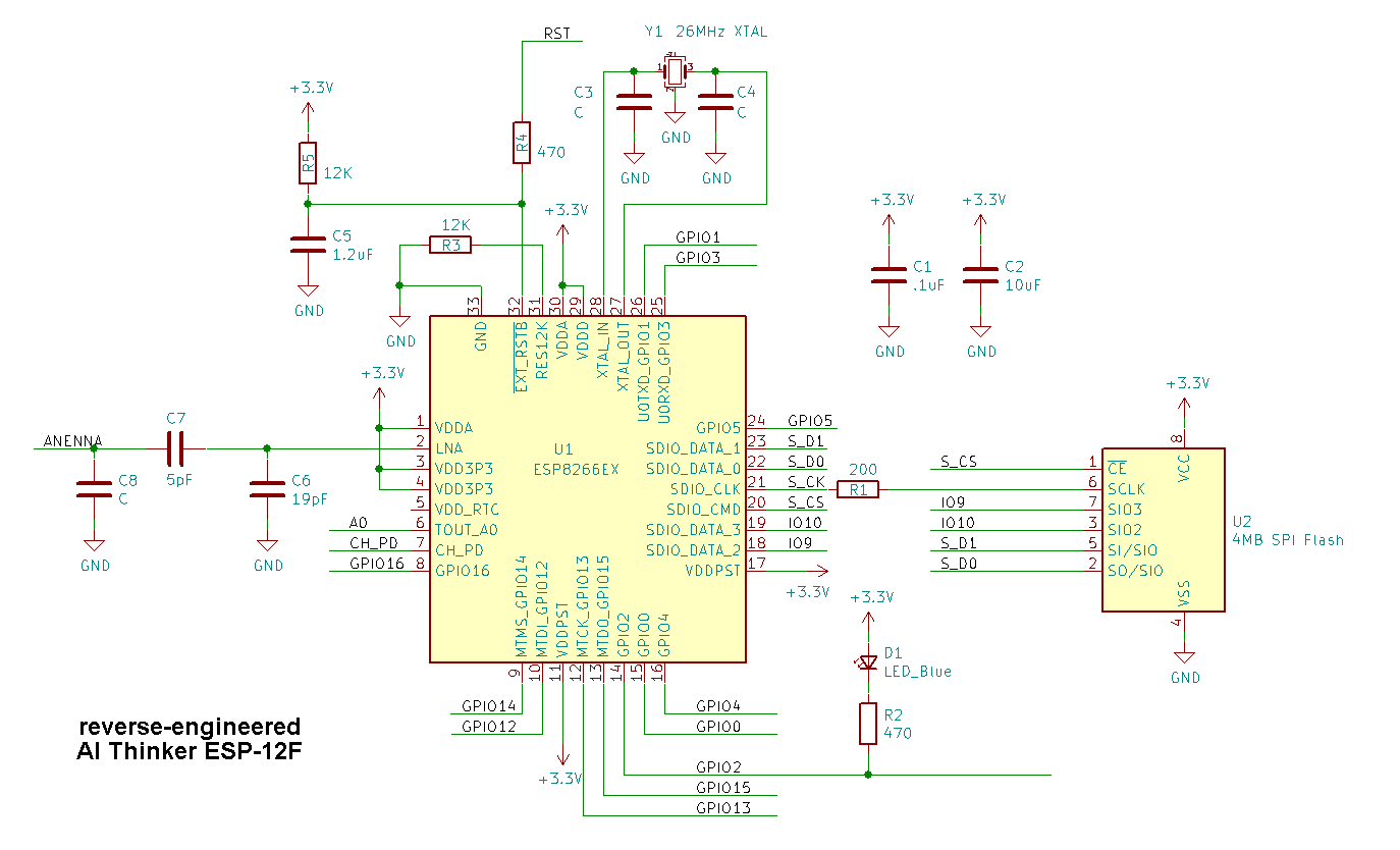
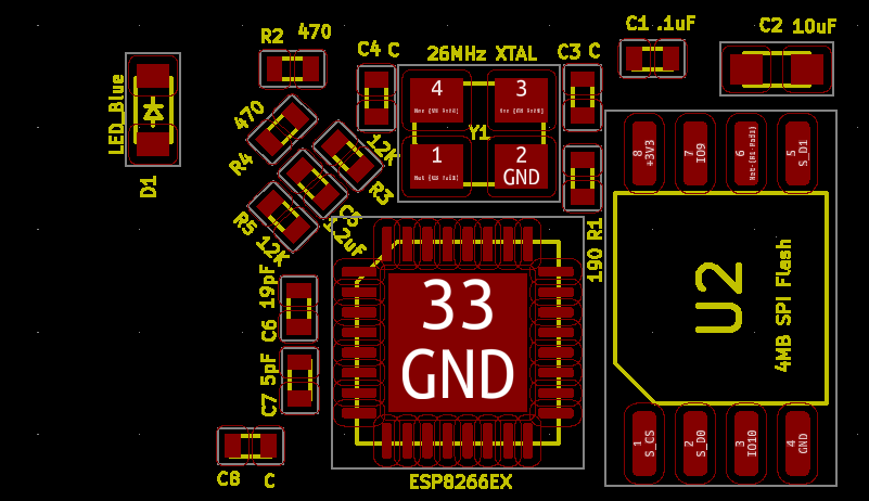
Tech-TX
on 23 Nov 2020
@Tech-TX Thanks for the updates.
I don't recall what you're using for a power supply
Another way to prove it would be to run a quality 3.3V power supply right to the CPU and flash, bypassing the LDO.
I tried all of them without success. (different LDO, an additional elco over the flash chip, external power supply etc)
At the other end, the wake problem also exists when WiFi is disabled:
ESP.deepSleep(1*1000000, WAKE_RF_DISABLED);
So I'm not sure if it is related to power in this case. I expect more the faulty flash chip, but the exchange with another SMD flash chip damaged the PCB accidentally.
Nice schematic. That's helpful. In my case R5 is 5k6 instead of 12k.
I did not notice R1. It does not exist on my version because it is shorted... Do you know if this resistor is needed?
Erriez
on 23 Nov 2020
I've seen a resistor like that on a few modules, and done it myself. It reduces the ringing at the Flash by matching the impedance of the source + trace to the destination. I suspect it's needed for their board or they wouldn't have added it. I'd have started with a 50 to 75 ohm resistor and then probed at the Flash to see what my clock looked like, and then adjusted the source-termination resistor to the sweet spot with minimal ringing. Since that R1 is a measured value, the resistor could be either 180 or 200 ohms in E24 values. If it's under-terminated, the Flash will see ringing. If it's over-terminated, the amplitude will drop at the Flash pin. Either value will likely work, though.
If your board doesn't have it, that's one possible source of the trouble you're having. That could cause erratic operation of the flash, even over such a short distance. Generally you want a terminated transmission line for clocks. High speed digital design is a bit of black magic and some rules of thumb. My rule for clocks is: always plan them early in the design and take great care later in the board layout. I'm also wicked careful with power and ground if I don't have planes.
For replacing SMD chips I don't care about saving, I gently cut the pins off close to the body with a razor knife (a sharp X-acto blade here in the US). Then I can remove the pins without damaging the pads. It's a bit late for that tip, though.

In that case, I was only removing the USB and LDO power hogs on a D1 Mini so I could measure the CPU current, so I didn't remove the bits of pin.
Tech-TX
on 24 Nov 2020
I will assume that for slow flash, the pulse duration with GPIO16 is not sufficient for normal operation.
To solve the problem, you need to increase the pulse duration.
Therefore, you can not put a pull-up resistor on pin_RST.
You can add a small capacity to the pin_RST.
Put the pulse duration shaper between GPIO16 and RST.
I will agree that 5.6K for the pull-up on Erriez' board is too strong. I would have used a 12K. The datasheet says that there is an internal pull-up resistor on EXT_RSTB, but it doesn't specify the value. I assume it is a weak PFET and cannot be measured externally easily. The other weak PFETs are around 50K, from measurements I made.
In other threads on ESP8266.com and here I have seen people try to extend the time of /EXT_RSTB and it did not help them waking from Deep Sleep.
In the diagram above, the C5 capacity is connected to the GPIO16 pin.
This is obviously a mistake. If C5 is indeed connected to GPIO16, then it is the cause of the problem.
C5 must be removed.
@nikolz0 I'm not sure what schematic you are looking at... the one I posted has C5 on EXT_RSTB, with a 470 ohm resistor going out to the RST pad on the ESP-12F module. Connecting GPIO16 to that RST pad works fine, either with a wire or a Schottky diode.
Tech-TX
on 25 Nov 2020
In the above diagram, C5, R5, and R4 at the RTC input create a pulse delay at the RTC input.
But these elements reduce the pulse duration with GPIO16.
It may make sense to remove these elements or change the value of C5.
See the documentation. It doesn't have these elements.
They may be needed when the power is turned on, but they worsen the ESP's output from sleep.
esp8266_hardware_design_guidelines_en.pdf
nikolz0
on 25 Nov 2020
@Erriez I may finally have an answer for your problem, if you still have any modules that won't wake up properly.
During /EXT_RSTB and for ~35ms after EXT_RSTB rises, GPIO15 is being driven to a weird level: 0.70V on my board. That's uncomfortably close to the 'undefined' input range for the pins (0.25xVIO to 0.75xVIO). If GPIO15 is seen as HIGH during the boot mode detection, then the chip goes into SDIO/SPI mode instead of Flash boot. I've verified that two different modules are doing the same thing (0.7V output on GPIO15). What I think may be happening is that your modules are a little bit above that, and the chip sees it as SDIO mode. SDIO could be your 'zombie mode' after Deep Sleep.
I'd like to recommend that you try a stronger pull-down resistor on GPIO15 to see if your modules wake properly. 5K or so should be sufficient.
On my gutted D1 Mini, I verified the pull-down on GPIO15 is 10K (9.9K measured). I wrote a quick little test, setting all GPIOs to OUTPUT, HIGH, then ran Deep Sleep and woke the chip up again. The test ONLY sets the outputs on power-up reset or external reset; they're unchanged after Deep Sleep Wake.
This first capture is with ESP.deepsleep(0), woken by an external reset:

This second capture is with ESP.deepsleep(5e6), woken by GPIO16 with a Schottky diode connection:

For both captures, the scope has a 1meg pull-up & 1meg pull-down so I can see if the pin tristates. The 1meg resistors plus the load of the scope will be somewhere around 0.83V if it's tri-stated. Since the pins are in 2uA drive (550K equivalent) during Deep Sleep, that pull-up/pull-down arrangement results in ~ 2.67V measured on the pins. When it comes out of Sleep it's 3.3V, as the 12mA OUTPUT HIGH drive predominates.
One other interesting item: the CPU is waking up ~2ms before GPIO16 drops low at the end of Deep Sleep. You can see it in the other pin states below, all done with ESP.deepsleep(5e6) and the same 1meg pull-up/pull-down:


I haven't seen this described in the Espressif docs, or in posts by anyone else. Deep Sleep Wake actually begins BEFORE GPIO16 drops. GPIO16 is not the trigger, it's being done internally by the RTC. GPIO16 seems to be letting the chip know that it's returned from Deep Sleep by briefly holding the EXT-RSTB pin low while it's already coming awake.

| GPIO1 | GPIO15 | GPIO0 | GPIO2 | Mode |
|:----:|:----:|:-----:|:-----:|---------------|
| 1 | 1 | X | X | SDIO/SPI |
| 1 | 0 | 0 | 1 | UART Download |
| 1 | 0 | 1 | 1 | Flash Boot |
| 0 | X | X | X | Chip Test |
Tech-TX
on 26 Nov 2020
I haven't seen this described in the Espressif docs, or in posts by anyone else. Deep Sleep Wake actually begins BEFORE GPIO16 drops. GPIO16 is not the trigger, it's being done internally by the RTC. GPIO16 seems to be letting the chip know that it's returned from Deep Sleep by briefly holding the EXT-RSTB pin low while it's already coming awake.
Hmm that's interesting.
What happens if you don't connect GPIO-16 and RST?
Is it possible the ESP (or some ESPs) could enter the programming mode if GPIO-15 is high enough when the ESP tries to wake itself while GPIO-16 and RST are not connected?
The use case I'm thinking off is to have GPIO-16 and RST connected via an external switch to allow/prevent the unit to wake up from deep sleep. But if the ESP then may somehow enter the flash mode and remain in that mode for a while draining the battery.
TD-er
on 26 Nov 2020
That's easy: you get the ets_main.c message, because it doesn't know what woke it up or where to go next. You'll get the same message if you use a resistor to connect GPIO16 to EXT_RSTB and the value is too high, as the EXT_RSTB pin never goes low enough to be recognized as a Deep Sleep Wake; the chip is awake, but can't figure out why.
ets Jan 8 2013,rst cause:2, boot mode:(3,6)
load 0x4010f000, len 3640, room 16
tail 8
chksum 0xd2
csum 0xd2
v4cc3d8a1
~ldets Jan 8 2013,rst cause:5, boot mode:(3,6)
ets_main.c
Tech-TX
on 26 Nov 2020
@Tech-TX Thanks for your deep investigation.
I'd like to recommend that you try a stronger pull-down resistor on GPIO15 to see if your modules wake properly. 5K or so should be sufficient.
I remember that I tried a pull-down resistor before on GPIO15. I've built it up on a breadboard and tried different pull-down resistors, including a 2k2, 4k7 and 10k, but all with the same result:
17:55:20.421 ->  ets Jan  8 2013,rst cause:2, boot mode:(3,6)
17:55:20.421 ->
17:55:20.421 -> load 0x4010f000, len 3584, room 16
17:55:20.421 -> tail 0
17:55:20.421 -> chksum 0xb0
17:55:20.421 -> csum 0xb0
17:55:20.421 -> v2843a5ac
17:55:20.421 -> ~ld
17:55:21.650 ->
17:55:21.650 ->  ets Jan  8 2013,rst cause:2, boot mode:(3,6)
17:55:21.650 ->
No further output
For my specific device, I think the flash can be a problem. I wish I had better news.
Erriez
on 26 Nov 2020
@Erriez I may have something else for you. I've been going back and forth between different designs, old Espressif docs and demonstrator boards, and current Espressif docs. Their oldest demo board ESP-LAUNCHER has a 5K pull-up on RST and a 100pF cap to ground, with a jumper block to GPIO16 for Deep Sleep (a wire). Currently they recommend a 0.1uF cap to ground on RST with a 10K pull-up. They also suggest a .1uF cap on the CH_PD pin. However, that violates their sequencing of power, then CH_PD, then RST rising. I'd boost the RST resistor to 20K with a .1uF cap, which is well above the 5.6K you have. It also means that series 470 ohm resistor in the RST line will allow the signal at the EXT_RSTB pin to more closely approach ground.
Old modules didn't have the 470 ohm series resistor on the reset logic going to the RST pin on the module, that came in with the ESP-12F. AI Thinker and Doit.am seem to both be using a 1uF cap on the RST line, which doesn't make sense as that adds a reel of 1uF caps when they're placing the board (they already have a 0.1uF cap on VCC).
The only mention of timing of RST that I've found is a minimum of 200us for an external reset to be recognized. Gee, that's an eternity for a chip running at 80MHz. That 200uS is likely because the CPU slows way down in Light Sleep, but I haven't tried to gauge it's speed in Light Sleep yet.
Reading everything, I think someone effed up a few years ago and didn't notice the leading period on the reset cap value, and it's stuck ever since, and everyone else copied it. That doesn't explain why my modules work and yours don't, but it's something where everyone has gone awry.
I'll draw up a quick schematic tomorrow. It's late and I'm tired tonight.
Tech-TX
on 30 Nov 2020
That 200uS is likely because the CPU slows way down in Light Sleep, but I haven't tried to gauge it's speed in Light Sleep yet.
Is it somewhere documented that the clock speed is lowered in light sleep?
Or is the external circuitry running on some actual RTC-like circuit which also keeps the RAM active and keeps the sleep timer?
It is like 6.6... clock cycles when running at the famous 32768 Hz any watch with a crystal uses
TD-er
on 30 Nov 2020
Espressif says the CPU clock is off during Light Sleep and Deep Sleep both, but I measured a variable difference of a few thousand micros() ticks across Light Sleep.
The external Reset processing in Deep Sleep (must be low for 200us) has to be done in the RTC since it's the only thing running a clock then. Maybe it's really sloppy on reset detection.
Tech-TX
on 30 Nov 2020
Say @Erriez ? I have something else to try, if you still have any modules that don't wake properly. It's not a 'fix', more a work-around.
Connect the CH_PD (EN) pin on the module to the RST pin (not the GPIO16 side) on the module. On my D1 Mini boards there's a pull-up resistor for CH_PD on the bottom near the pull-up resistor for RST that's convenient to solder to, unknown how your boards are laid out but I presume something similar as the pins on the ESP-12F are near neighbors.
I ran it here with a Deep Sleep loop, and although it's showing rst cause:1 boot mode(3,6) instead of rst cause:2 boot mode(3,6) it seems to be working OK. That's not as comforting as it may seem since mine have never emulated The Walking Dead, but it appears to work in a modified Deep Sleep that way. It won't help you if you're planning on using the RTC RAM to store things during Deep Sleep, as dropping CH_PD should wipe the RAM.
This thread has gotten so ridiculously long that I can't tell if you've already attempted this.
By the way, I tried putting my D1 Mini in 'self test' by booting with GPIO15 high, and all I get is a "_Waiting for host_" message. I haven't seen anyone mention that, so zombie mode isn't self test.
Tech-TX
on 6 Dec 2020
@Tech-TX
if you still have any modules that don't wake properly
Yes, I've several unstable ESP8266 devices which cost me too much time now. Even in the field some devices can hang forever unexpectedly and draining the battery. My fallback is the old good ATMega328 with STX882 433MHz transmitter to send sensor data to a base station connected to Ethernet. This works reliable for years and the lifetime of a 18650 battery is much higher. The price does not matter, so I try to revive my old projects.
This thread has gotten so ridiculously long that I can't tell if you've already attempted this.
Correct. In the mean time Travis CI dropped free support, so I've a headache to move my Arduino Github projects away to another free continues integration build server. To be honest, I'd like to continue with my projects and stop this investigation. I hope you understand.
Erriez
on 7 Dec 2020
Thank you all for the hard work put into this investigation. It took me many days to struggle with this deep sleep issue until I found this thread.
I use Wemos D1 mini (copys maybe) for my project. Same batches different behaviours with the deep sleep.
The workaround code bí @nikolz0 mentioned above works perfectly for me too.
A picture I wanted to share. I found that I seem to have 3 types of boards and the one on the top works with the original deep sleep function, the below 2 don't. Not sure what those pieces do, but at least I differentiate them by looking at it.

 doharadam
on 8 Dec 2020
doharadam
on 8 Dec 2020
I recommend using nodemcu only for debugging programs without sleep mode.
It is better to put ESP-12 in working projects.
The nodemcu module (Wemos ) can be easily replaced with an ESP-12, three resistors, one Schottky diode, two buttons, and any USB-UART adapter. In this case, only one adapter is needed for any number of ESP-12.
nikolz0
on 8 Dec 2020
@doharadam the top of the boards would tell more. The differences on the bottom don't matter. The middle module for instance is using the CH340C USB chip which has an internal crystal, so they left off the external crystal. The only real difference I see is that the bottom two boards have more greyish silkscreen, so likely came from the same low-quality PCB fab. I'll bet the ESP-12F modules on the bottom two are identical, and the RF shield is slightly different on the top one. It's possible it's all the same no-name clone ESP-12F module. In Erriez' case, some of his boards work, some don't, and they all appear to be from the same batch. It's something that's right on the edge of working properly.
Tech-TX
on 10 Dec 2020
And what may be the parameter to tip them over the edge (either way)?
shape/timing of the wake pulse? Delay on the enable pin? Max current of the voltage regulator? Or something else (or all of them :) ) ?
TD-er
on 10 Dec 2020
Don't know, as I don't have anything here that goes zombie. If I knew for sure what was breaking with those cheap clone ESP-12F modules I'd mark this _zombie mode_ thread as 'solved' and move on. I've asked a couple of the eBay suppliers if they had any returned boards that the buyer complained wouldn't come out of Deep Sleep, but they didn't get them back, only sent replacements. I don't want to buy a boatload of cheap junk merely to see if I can get one or two that don't work for troubleshooting purposes.
So far we've had:
1) replace the flash and it works (might be the default 75% pin drive in the XTX chips)
2) add a 47K pull-up on MISO (GPIO12) and it works (debatable... doesn't make any sense)
3) use a better power supply (could also be a dropout across the Schottky diode on the USB input)
4) use a wire / Schottky / low value resistor for the GPIO16 > RST pin
The only time I had problems was when I used a resistor to connect GPIO16 > RST. Most likely the EXT_RSTB pin wasn't going low enough to be detected due to the series 470 ohm resistor inside the module. With a wire or a Schottky / germanium diode, it always works for me.
I've tested on the following boards and modules, 2 to 3 of each type:
AI Thinker ESP-12F modules
AI Thinker ESP-12S modules
AI Thinker ESP-07S modules
DOIT ESP-12F module on a clone D1 Mini (several different boards, as I have > 30 of them)
clone NodeMCU DevKit v0.9 with a DOIT ESP-12F module onboard (have 2)
clone D1 Mini Pro (have 1)
WeMos NodeMCU LUA (have 1, possibly authentic and not a clone)
DOIT ESP-M3 (ESP8285) (have 10)
clone ESP-01S (that was a pain in the @ss....) (have 1)
Elsewhere people have complained of Deep Sleep issues with ESP-12F modules on D1 Mini boards that have DOITING on the RF shield. I don't have any of these and can't confirm. It _should_ be the same as the DOIT modules (same company) but possibly they used a different Flash manufacturer on these newer modules. Could also be user error.
Tech-TX
on 12 Dec 2020
You can put a monovibrator between GPIO16 and RST and significantly increase the pulse duration.
You can set the tpl51xx timer and forget about this problem, get a sleep current of 3 ua instead of 20 ua.
nikolz0
on 13 Dec 2020
I don't believe _zombie mode_ relates to the pulse at EXT_RSTB. When my modules have a poor pulse, they display the 'ets_main.c' message, not _zombie mode_. If the RST pulse doesn't go low enough to be detected as LOW, arrives too late or is too brief, you should get the 'ets_main.c' as the boot code can't determine which bin to load.
Tech-TX
on 13 Dec 2020
Related issues
 Khorne13
·
3Comments
Khorne13
·
3Comments
 treii28
·
3Comments
treii28
·
3Comments
 Geend
·
3Comments
Geend
·
3Comments
 hoacvxd
·
3Comments
hoacvxd
·
3Comments
 gosewski
·
3Comments
gosewski
·
3Comments
Most helpful comment
No new info. The only 2 known workarounds are the code above and the 47K pullup on MISO, and even that doesn't help all cases.
It would be interesting if somebody could reverse engineer the sdk deep sleep calls and figure out the difference vs the above code, especially the wakeup param. We could then implement our own version of deep sleep.