Arduino: More than 3 attachInterrupts() don't seem to work
Please fill the info fields, it helps to get you faster support ;)
if you have a stack dump decode it:
https://github.com/esp8266/Arduino/blob/master/doc/Troubleshooting/stack_dump.rst
for better debug messages:
https://github.com/esp8266/Arduino/blob/master/doc/Troubleshooting/debugging.rst
----------------------------- Remove above -----------------------------
Basic Infos
Hardware
Hardware: wemos mini pro
Core Version: V2.4.0
Description
i have 4 x flow meters on D1, D5, D6, D7 respectively.
I found that when I do the `attachInterrupt(sensorPin, pulseCounter, FALLING); function that the 3rd and 4th function bind in such a way that only 3 x flow meters interrupts are active.
Is there a limitation on number of interrupts that ESP8266 can handle ?
Settings in IDE
Module: ?Generic ESP8266 Module?
Flash Size: ?4MB/1MB?
CPU Frequency: ?80Mhz?
Flash Mode: ?qio?
Flash Frequency: ?40Mhz?
Upload Using: ?OTA / SERIAL?
Reset Method: ?ck / nodemcu?
Sketch
#define sensorPin_1 D1
#define sensorPin_2 D5
#define sensorPin_3 D6
#define sensorPin_4 D7

volatile byte pulseCount[4];

void setup() {

Serial.begin(115200);

   attachInterrupt(sensorPin_1, pulseCounter_1, FALLING);
    attachInterrupt(sensorPin_2, pulseCounter_2, FALLING);
    attachInterrupt(sensorPin_3, pulseCounter_3, FALLING);
    attachInterrupt(sensorPin_4, pulseCounter_4, FALLING);

}

//************************************************************
//======== Interrupt Service Routine for Flow Meter ==========

void pulseCounter_1()
{
  // Increment the pulse counter
  pulseCount[0]++;
}

void pulseCounter_2()
{
  // Increment the pulse counter
  pulseCount[1]++;
}

void pulseCounter_3()
{
  // Increment the pulse counter
  pulseCount[2]++;
}

void pulseCounter_4()
{
  // Increment the pulse counter
  pulseCount[3]++;
}
void loop() {
 Serial.print ("Pulses are = ");
Serial.print (pulseCount[0]);
Serial.print (pulseCount[1]);
Serial.print (pulseCount[2]);
Serial.print (pulseCount[3]);
}
Debug Messages
messages here
 mars000
All 18 comments
Hi - I just read here http://gammon.com.au/interrupts that there seems to be a limit to 3 pin change interrupts ? does this limitation also apply to ESP8266 ?

mars000
on 6 Mar 2018
@igrr - hi ivan
sorry for direct question but really need to solve issue I have with inability to have more than 3 gpio interrupts setup on Wemos mini pro. I use attachInterrupt function as per example above but what happens are interrupts for sensor_Pin3 and sensort_pin4 get combined. Is there a limit to number of pins that can assigned interrupts in one sketch ? (BTW: i also tried attachInterrupt(digitalPinToInterrupt(sensorPin_3), pulseCounter_3, FALLING);
mars000
on 7 Mar 2018
Your interrupt service routines need to be in ram, not flash. Make them all look like this...
void ICACHE_RAM_ATTR pulseCounter_1()
{
// Increment the pulse counter
pulseCount[0]++;
}
 MarkusAD
on 7 Mar 2018
MarkusAD
on 7 Mar 2018
hi - thanks for your suggestion. I implement changes but unfortunately not making any difference.
i.e. I seem to get same number for pulseCount[2] and pulseCount[3] , as if the interrupts are connected/entangledin some way. The only way to resolve is to keep it at max 3 interrupts.
mars000
on 7 Mar 2018
Works for me... where are your pinMode() statements in setup()? For each pin...
pinMode(sensorPin_1, INPUT_PULLUP);
attachInterrupt(digitalPinToInterrupt(sensorPin_1), pulseCounter_1, FALLING);
MarkusAD
on 7 Mar 2018
yes I have in setup beforeattachInterrupt(xxxx) the following:
  pinMode(sensorPin_1, INPUT_PULLUP);
  pinMode(sensorPin_2, INPUT_PULLUP);
  pinMode(sensorPin_3, INPUT_PULLUP);
  pinMode(sensorPin_4, INPUT_PULLUP);
BTW: is it important/critical to use digitalPinToInterrupt -- seems to make no difference when if I do or dont' use it.
Any chance you can share your code that validates it works. As noted for me it sometime combines Int3 and Int 4 and sometimes it doesn't.
mars000
on 7 Mar 2018
Same as your code, only other thing I changed was loop()...
```javascript
void loop() {
char buf[16];
sprintf(buf, "%03d %03d %03d %03d",
pulseCount[0], pulseCount[1], pulseCount[2], pulseCount[3]);
Serial.println(buf);
delay(1000);
}
MarkusAD
on 7 Mar 2018
edited: sorry for the typo, sprintf() vars should be 3 characters wide.
MarkusAD
on 7 Mar 2018
I see - but how are you generating the input i.e. you using 4 flow sensors in order to verify pulses ?
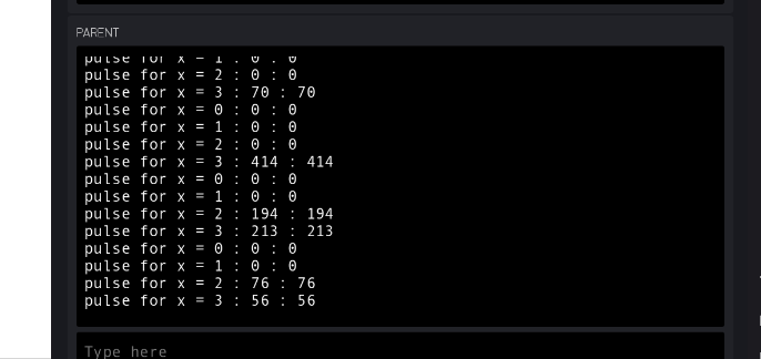
To provide more context see screenshot below. I count pulses received from x = 0 to 3 representing pulseCount[0] to [3]. You will notice when flowmeter[2] two is spinning and generating FALLING pulses it also shows pulses for flowmeter[3]; even though flowmeter[3] in this case was not spinning.
mars000
on 7 Mar 2018
I was just testing each pin with a jumper to ground, but seems to work ok, they all respond individually.
MarkusAD
on 7 Mar 2018
try using actual gpio pin numbers instead of the arduino digital pin aliases?
D1 = 5
D5 = 14
D6 = 12
D7 = 13
MarkusAD
on 7 Mar 2018
@mars000 like @MarkyAD wrote I notice you state Generic ESP8266 so how would the D references work?
 pieman64
on 7 Mar 2018
pieman64
on 7 Mar 2018
thats probably it, I compiled for my actual board (lolin).
MarkusAD
on 7 Mar 2018
sorry I copied my code from another editor. I actually have the following in the code:
(btw: i did now change attachInterrupt with actual GPIO number. see below. However my test still show same intermittent issue. I'm beginning to wonder if its my wiring setup.
I have same +5V and GND going to each flow meter. And separately I have data pins coming back to respective GPIO pins on Wemos mini pro. I do have this running over about 100M cat6 so maybe come long distance signally issues ?
// Pins mapping For Wemos Mini and D1 R2 to ARDUINO GPIO
#define D0 16   // NOTE: this GPIO16 does not support interrupts
#define D1 5    // NTE: avoid using GPIO6 to GPIO11 for Interrupts
#define D2 4
#define D3 0
#define D4 2
#define D5 14
#define D6 12
#define D7 13
#define D8 15
#define RX 3
#define TX 1

#define sensorPin_1 D1
#define sensorPin_2 D5
#define sensorPin_3 D6
#define sensorPin_4 D7

volatile byte pulseCount[4];

void setup() {

Serial.begin(115200);

pinMode(sensorPin_1, INPUT_PULLUP);
  pinMode(sensorPin_2, INPUT_PULLUP);
  pinMode(sensorPin_3, INPUT_PULLUP);
  pinMode(sensorPin_4, INPUT_PULLUP);

 attachInterrupt(digitalPinToInterrupt(5), pulseCounter_1, FALLING);
    attachInterrupt(digitalPinToInterrupt(14), pulseCounter_2, FALLING);
    attachInterrupt(digitalPinToInterrupt(12), pulseCounter_3, FALLING);
    attachInterrupt(digitalPinToInterrupt(13), pulseCounter_4, FALLING);

}

//************************************************************
//======== Interrupt Service Routine for Flow Meter ==========

void ICACHE_RAM_ATTR pulseCounter_1()
{
  // Increment the pulse counter
  pulseCount[0]++;
}

void void ICACHE_RAM_ATTR pulseCounter_2()
{
  // Increment the pulse counter
  pulseCount[1]++;
}

void void ICACHE_RAM_ATTR pulseCounter_3()
{
  // Increment the pulse counter
  pulseCount[2]++;
}

void void ICACHE_RAM_ATTR pulseCounter_4()
{
  // Increment the pulse counter
  pulseCount[3]++;
}
void loop() {
 Serial.print ("Pulses are = ");
Serial.print (pulseCount[0]);
Serial.print (pulseCount[1]);
Serial.print (pulseCount[2]);
Serial.print (pulseCount[3]);
}
I wonder if it may have to do
mars000
on 7 Mar 2018
i just tried it over a much shorter distance of cable i.e. 1 m vs 100m and seems to works better. I have a strong suspicion that over long cable distances there could be some sort of interference - I don't know why to be honest at this stage.
mars000
on 7 Mar 2018
Crazy stuff always happens with long cable runs, voltage sag and/or current starvation due to the resistance of the wire, noise getting on signal lines, crosstalk between individual lines, etc. If you've got extra wires in the bundle try using multiple wires in parallel for +V and ground or giving each sensor its own pair (stay with how the pairs are twisted in the bundle) for signal and ground.
Anyway the code does work and its not a core problem, suggest to close.
MarkusAD
on 7 Mar 2018
thanks all for your assistance. I would conclude its a wiring issue and the interrupts work.
mars000
on 7 Mar 2018
Related issues
 hoacvxd
·
3Comments
hoacvxd
·
3Comments
 gosewski
·
3Comments
gosewski
·
3Comments
 dariopb
·
3Comments
dariopb
·
3Comments
 tiestvangool
·
3Comments
tiestvangool
·
3Comments
 mark-hahn
·
3Comments
mark-hahn
·
3Comments
Most helpful comment
Your interrupt service routines need to be in ram, not flash. Make them all look like this...
void ICACHE_RAM_ATTR pulseCounter_1()
{
// Increment the pulse counter
pulseCount[0]++;
}