Arduino-esp32: Arduino board support/definition for TTGO T1 (v1.3+)
A board variant for TTGO-T1 V1.3 is needed.
TTGO-T1 V1.3 is a board based on ESP32 with a TF (microSD) card slot on the board. It is similar to the existing hardware/esp32/1.0.2/variants/ttgo-lora32-v1/pins_arduino.h but instead of LoRa it has microSD on board.
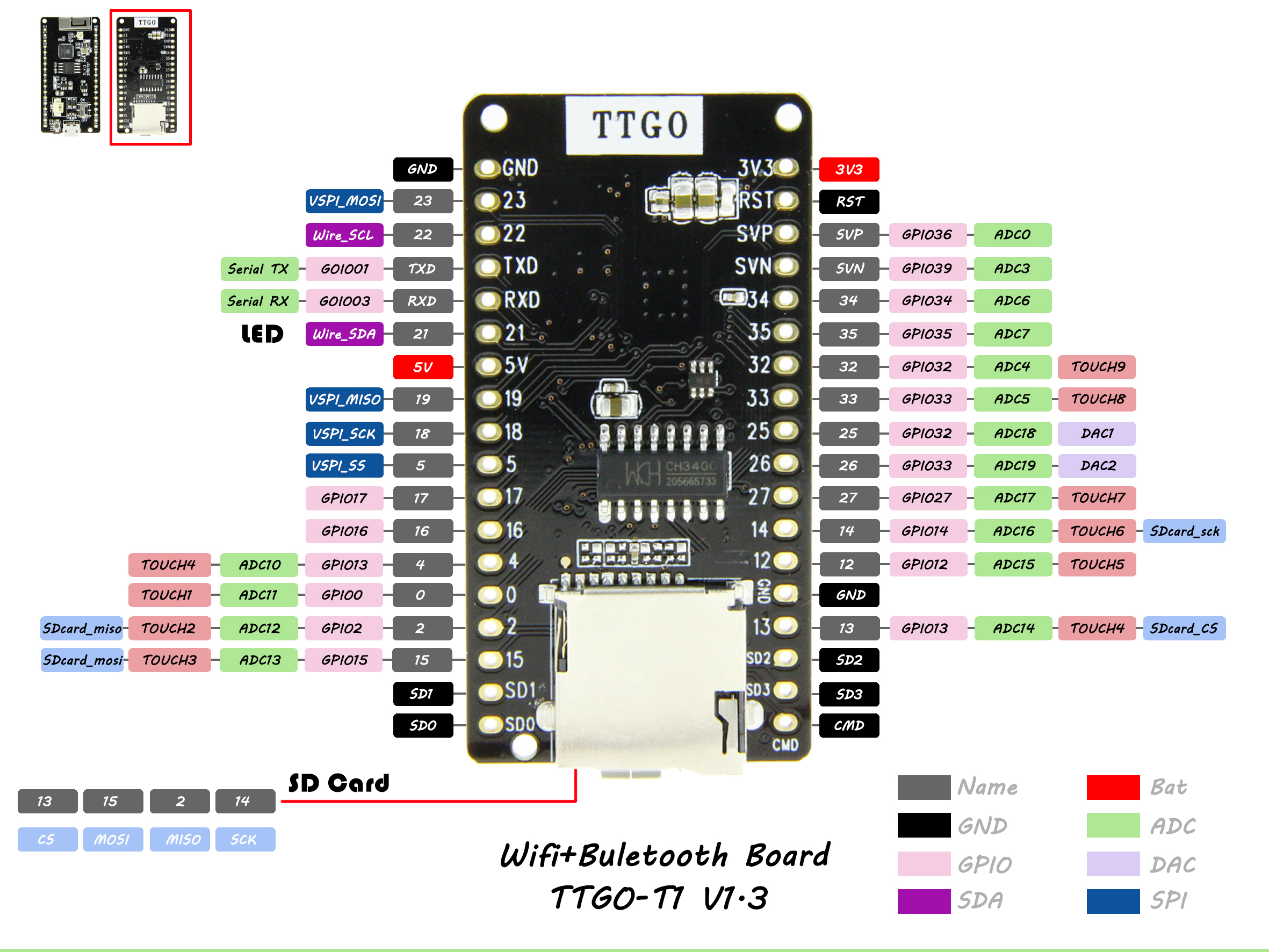
Looking at the pinout diagram my question is, how can we get SD.begin() to use GPIO13 for CS, GPIO15 for MOSI, GPIO2 for MISO, GPIO14 for SCK
static const uint8_t SD_SS    = 13;
static const uint8_t SD_MOSI  = 15;
static const uint8_t SD_MISO  = 2;
static const uint8_t SD_SCK   = 14;
while keeping, for all other devices,
static const uint8_t SS    = 18;
static const uint8_t MOSI  = 23;
static const uint8_t MISO  = 19;
static const uint8_t SCK   = 5;
so that the microSD card can be used while other SPI devices can still be attached to the broken out pins?
 probonopd
All 6 comments
you just call
SPI.begin(14, 2, 15, 13);
before
`SD.begin();
check void begin(int8_t sck=-1, int8_t miso=-1, int8_t mosi=-1, int8_t ss=-1);
in
https://github.com/espressif/arduino-esp32/blob/master/libraries/SPI/src/SPI.h#L55
 luc-github
on 3 May 2019
luc-github
on 3 May 2019
Thanks @luc-github
probonopd
on 3 May 2019
There is also the i2c pins, the built-in LED is on pin 22 and from my experience causes problems for i2c on that default pin.
 atanisoft
on 3 May 2019
atanisoft
on 3 May 2019
Reopening, since having a board definition file would probably still be a good thing.
probonopd
on 3 May 2019
I'll see if I can create a variant this weekend for this.
atanisoft
on 3 May 2019
Submitted a PR for the board definition, opted for override SS/MISO/MOSI/SCK with the SD defaults to make it easier for end users. SS needs to be overridden for all SPI devices usually anyway so it doesn't hurt to share the other pins.
atanisoft
on 5 May 2019
Related issues
 mpatafio
·
4Comments
mpatafio
·
4Comments
 maxgerhardt
·
3Comments
maxgerhardt
·
3Comments
 lonerzzz
·
3Comments
lonerzzz
·
3Comments
 merlinschumacher
·
4Comments
merlinschumacher
·
4Comments
 AsafFisher
·
4Comments
AsafFisher
·
4Comments
Most helpful comment
you just call
SPI.begin(14, 2, 15, 13);before
`SD.begin();
check
void begin(int8_t sck=-1, int8_t miso=-1, int8_t mosi=-1, int8_t ss=-1);in
https://github.com/espressif/arduino-esp32/blob/master/libraries/SPI/src/SPI.h#L55